Arcade Claw Machine/ Prize Game with Arduino
Oct 26 2019.
Well I never released this project as a DIY kit. It was just to demanding to support. So here are the CAD files. All of them: wood frame and the 3D printed parts. Even the full code.
I'm releasing them as I have plans to overhaul this into something about 2/3rd size and really flex on what I've learned. This is actually my favorite project I've created, it deserves to be shared. The design survived hundreds of users at many game shows. It's ready for the world. Happy making!

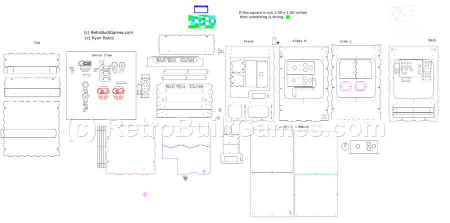
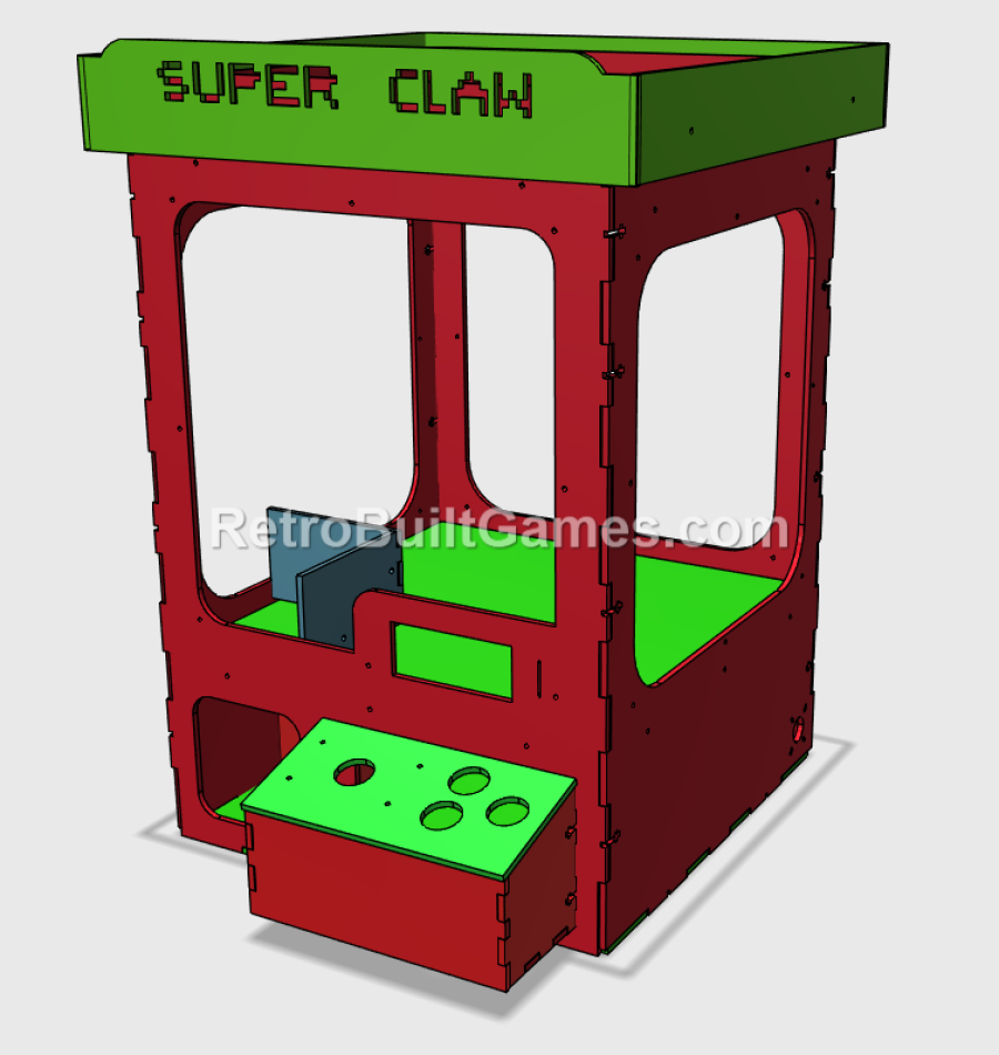
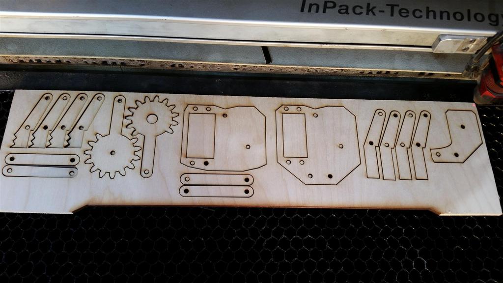
Wood and acrylic body panels
Claw Machine 4_v0_58.svg
Scalable vector image [369.0 KB]
Mainly X,Y,X gantry parts. STLs and Autodesk 123D files included.
Claw Machine ver_Four 3D parts.zip
Compressed archive in ZIP format [8.0 MB]
May require heavy edits (changing Pins) if deviating from the electrical design.
Claw_machine_AccelStepper_v0_67_PCBv4.ra[...]
Compressed file archive [5.3 KB]
Made with Eagle CAD v7.4.0
Claw Mchn v4 PCB Arduino Mega 2560.zip
Compressed archive in ZIP format [56.5 KB]
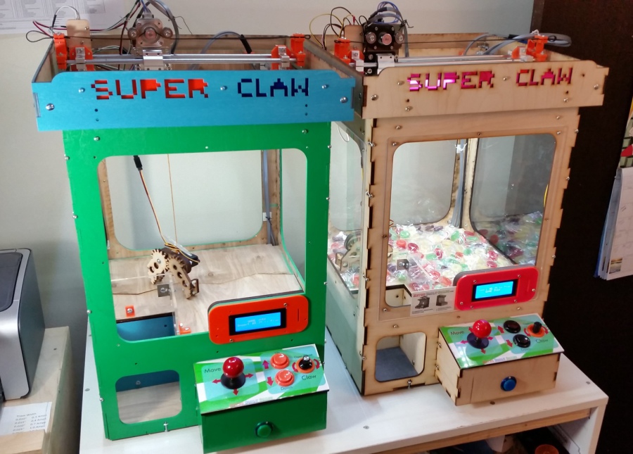
May 4, 2017
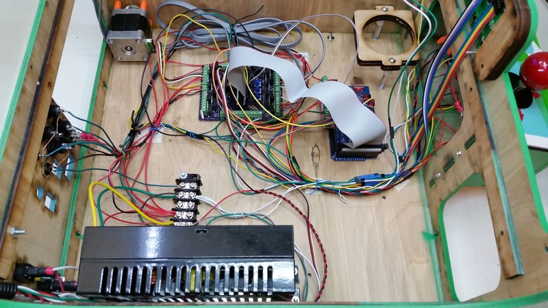
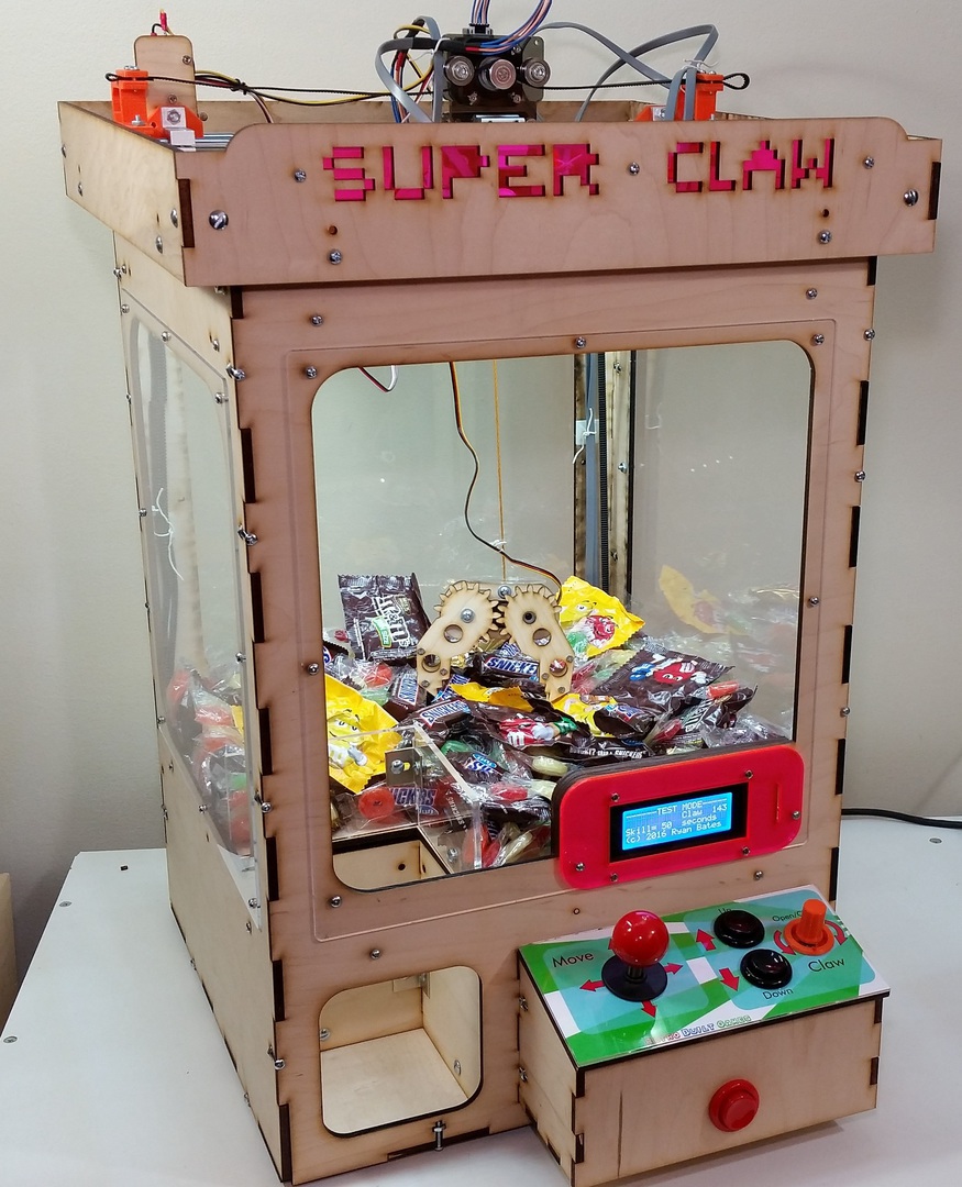
Built a new claw machine (v4) with the new PCB. Everything checks out OK.
March 22, 2017
Got the new claw machine PCB assembled. I will have to revise the code, as the pinouts are all different on this board vs previous claw machine iterations. Again, the posted code on my site is
not 1-to-1 compatible with this new PCB; lots of pin numbers were changed.
Jan 12, 2017
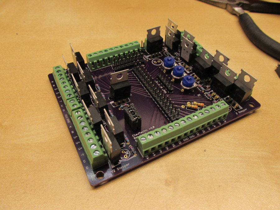
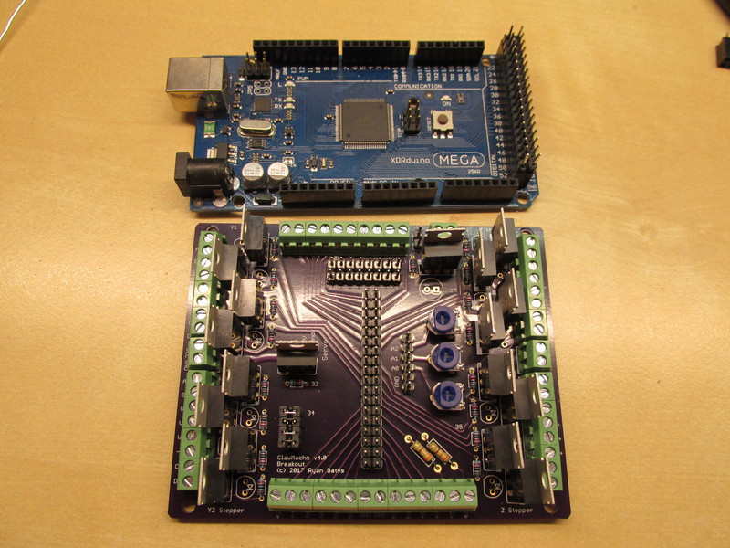
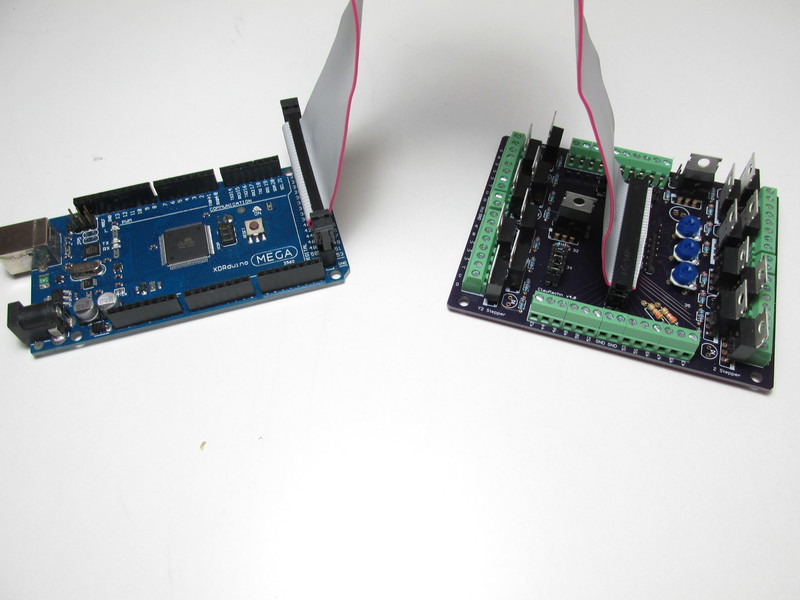
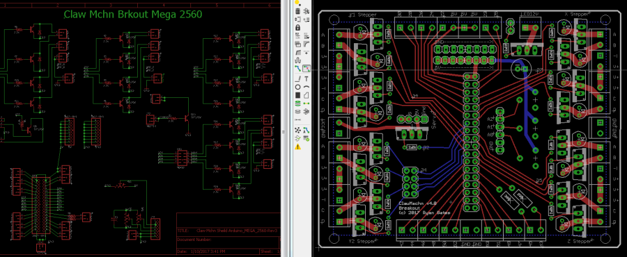
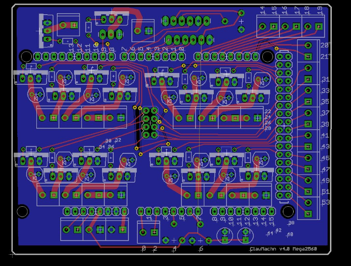
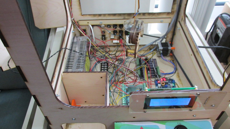
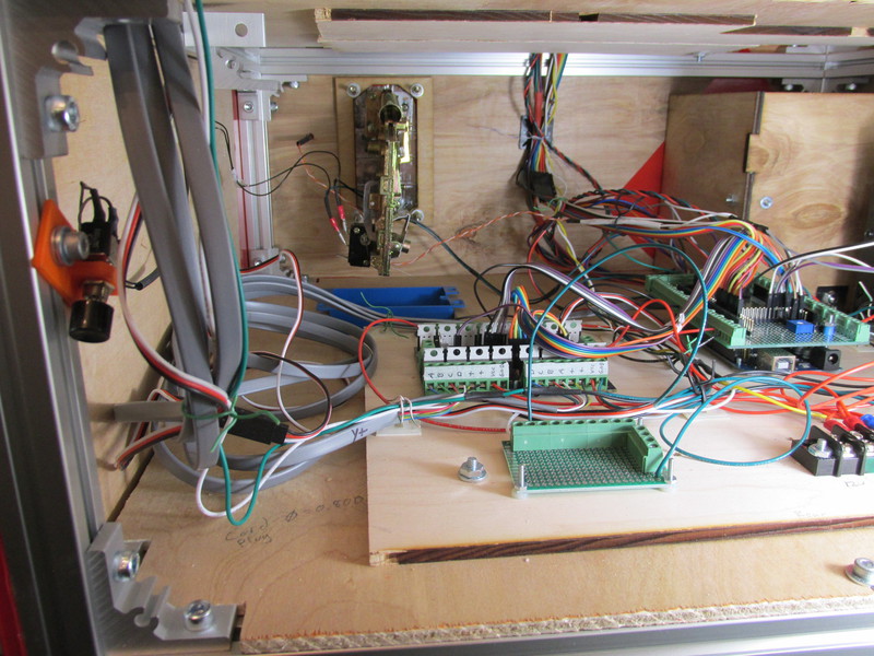
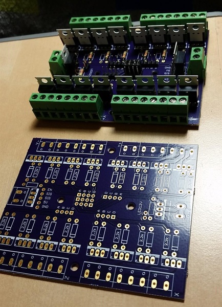
The claw machine motor pcb needed a more thoughtful solution to the mess of electronics a claw machine requires. My first solution (scroll wayyy down) was to connect motors. This worked fine, but after connecting all the limit switches, user controls and operator contols the wiring was organized like wet spaghetti. The Arduino Mega brand and clone boards do not have screw terminals only just female headers -not all that convienent when terminating wires.
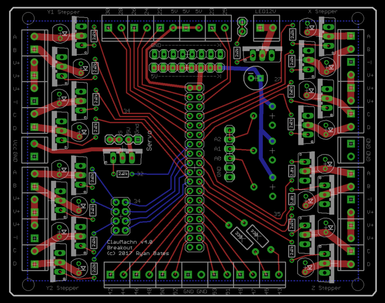
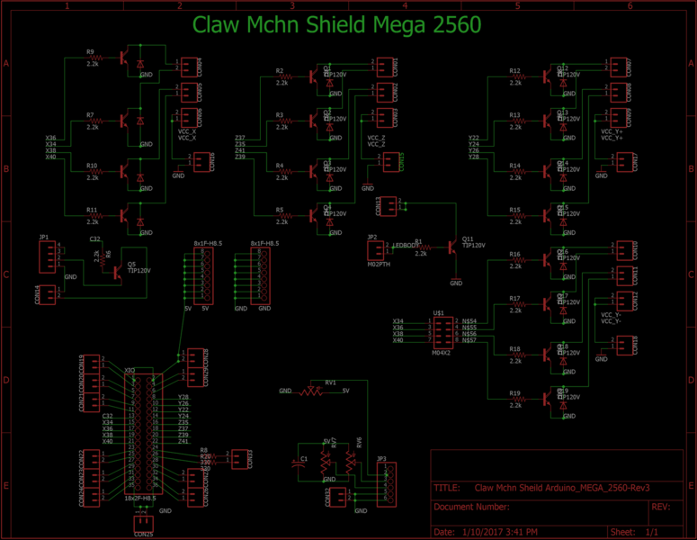
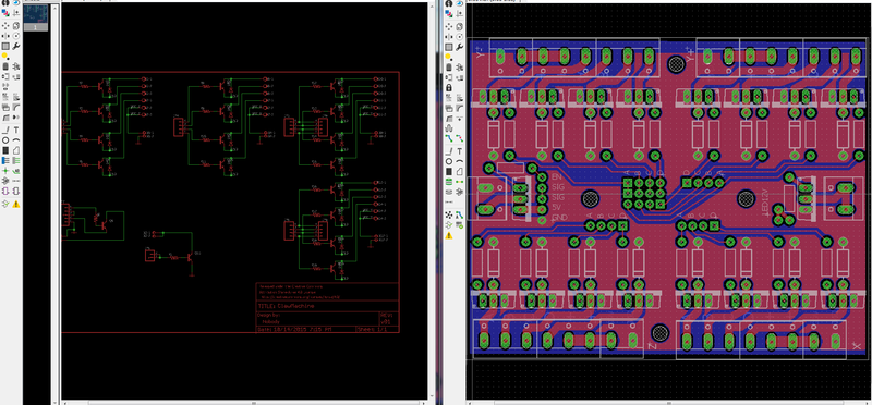
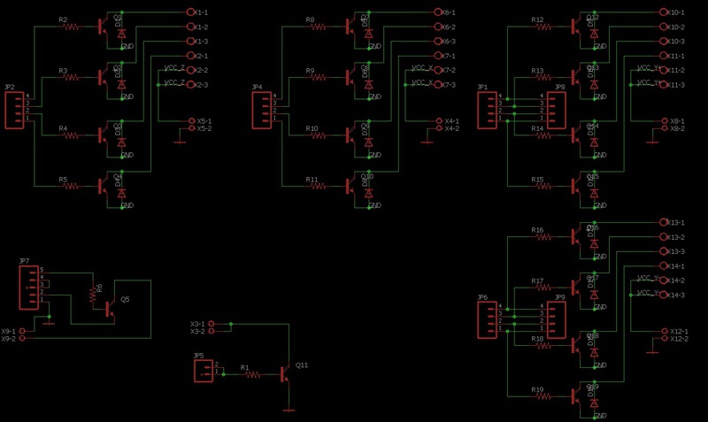
I started with a shield for the Mega 2560, however working around the header made for a messy layout and hard to reach terminals. The IDC looking header on the Mega is a good collection of pins and in the end, after 2 more revisions I settled on this PCB layout. I've ordered a batch of 10. A 36 or 40 IDC cable will breakout the Arduino Mega 2560 main header to screw terminals and the bipolor stepper drive portion of this board.
This PCB can drive 4 unipolar stepper motors marked as X, Y1, Y2, and Z. For steppers Y1 and Y2 there are male headers on the board that can be jumpered to bridge the connections of pins 34,36,38,40. The reason is if you are using two stepper motors for the Y axis ( one on each side, facing opposite of eachother). This takes the Y1 Stepper connections and mirrors them as Y2. So the both Y1 and Y2 steppers trigger in unison but rotate opposite as they are mirrored from each other.
 First iteration- MEGA2560 shield. Scrapped
Nov 30, 2016
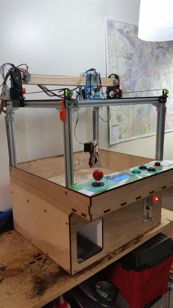
Beta assembly complete. Things went rather well.
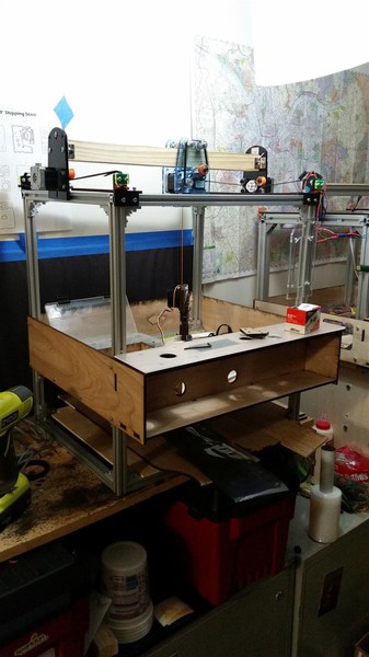
Octorber 31, 2016
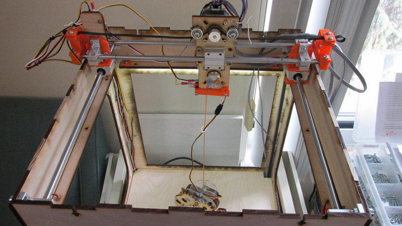
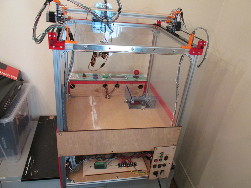
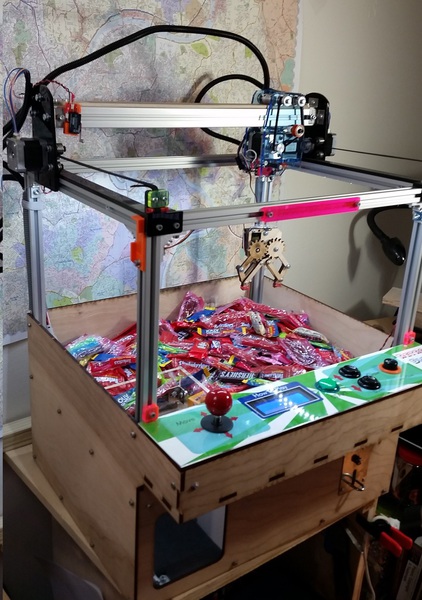
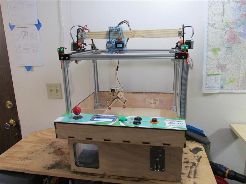
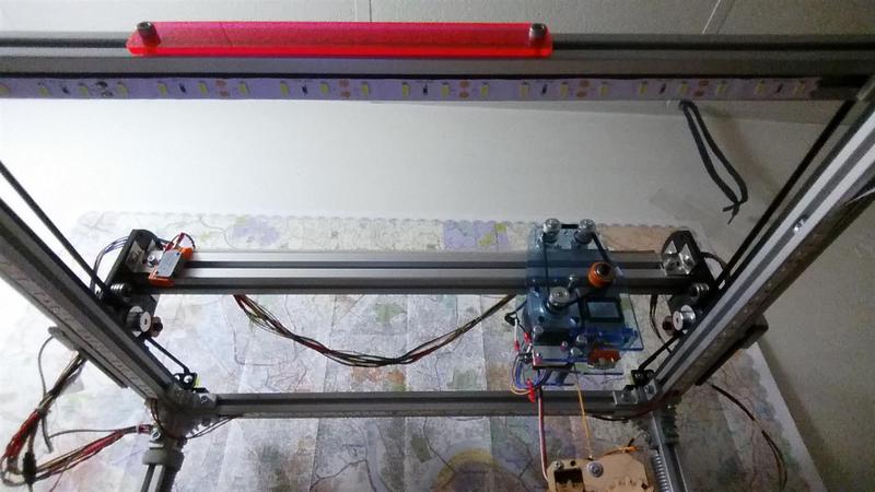
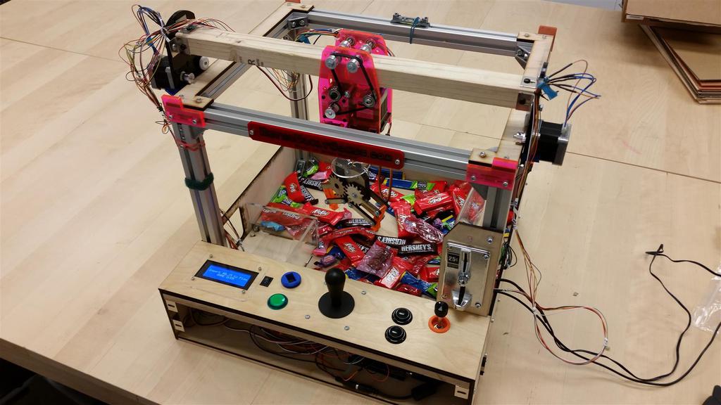
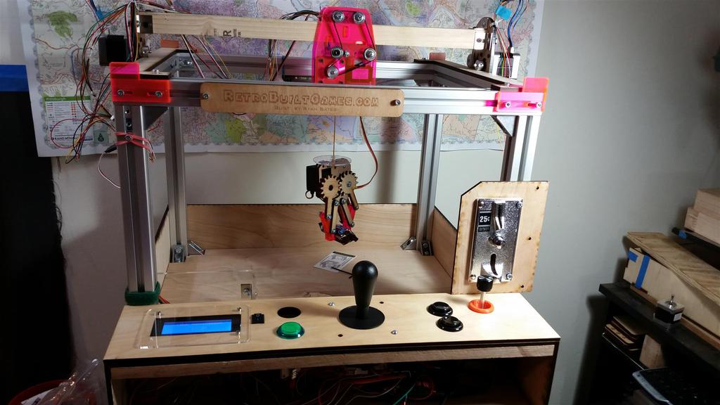
Consider this the alpha build of Claw Machine Version 4. In summary I've cut the parts list by half and the build cost by half. It also looks more like a calw machine proportion wise. The frame and body is all wood and gantry is comprised of 3D printer linear rails and bearing blocks. Super affordable. This design is easier to build than version 1 through 3. Way easier.
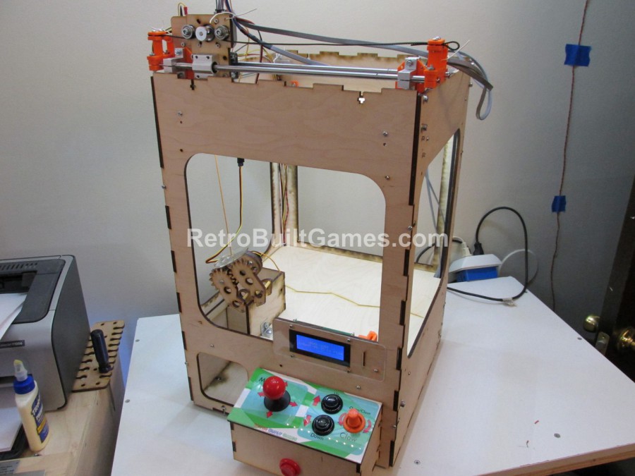
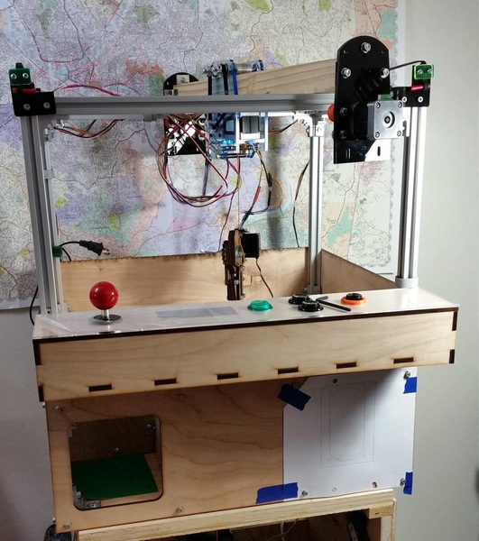
When designing and building this alpha machine, I was not sure how tall the gantry would be. It sticks out higher as the motors and mechanics need to occupy space; you either build upwards or outwards. Better to build upward than out. Mounting motors on the same plane as the gantry's travel (X and Y) reduces the area the claw can get to. The X gantry motor was mounted in the travel path, however, the Z motor was hung below, and the Y gantry motor was mounted under the prize floor. A long belt loop connects the Y gantry to the Y motor. The gantry is what gives me the most issues. It's a balancing act between simple design (cost) and function (reliability).
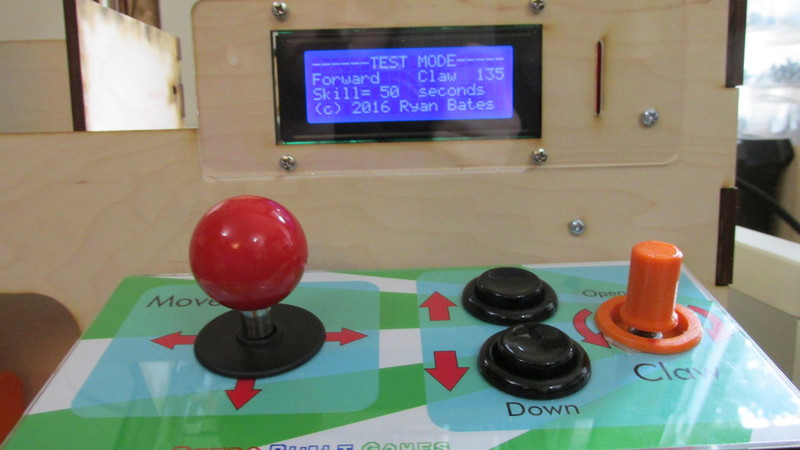
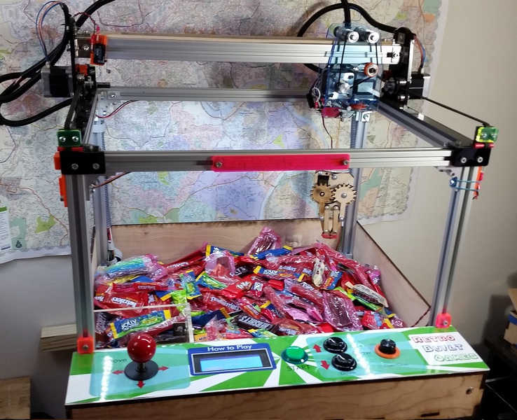
Software has some new features, specifically a "test" mode. This can be used for troubleshooting the input controls and just checking the mechanical movement of the machine. The test mode skips power the gantry (no timer like when playing the game-mode) and calls out when any input is pressed. Test mode also shows the servo position in degrees and the timers for the selected game (Skill or Luck) mode.
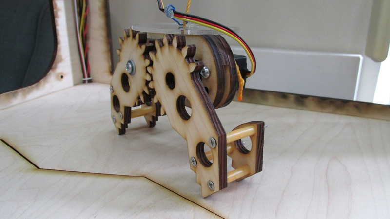
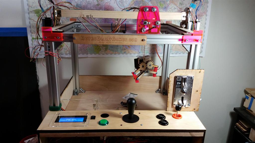
The claw also got revised again (4th time). Still sticking with an analog claw, but went for balance and simplicity. I am pleased that this claw design will stand upright when dropped to the prize floor.
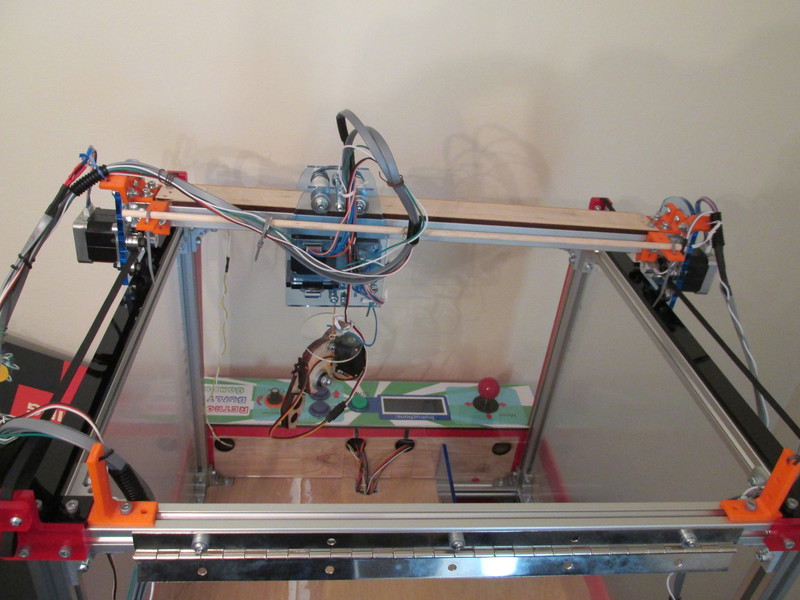
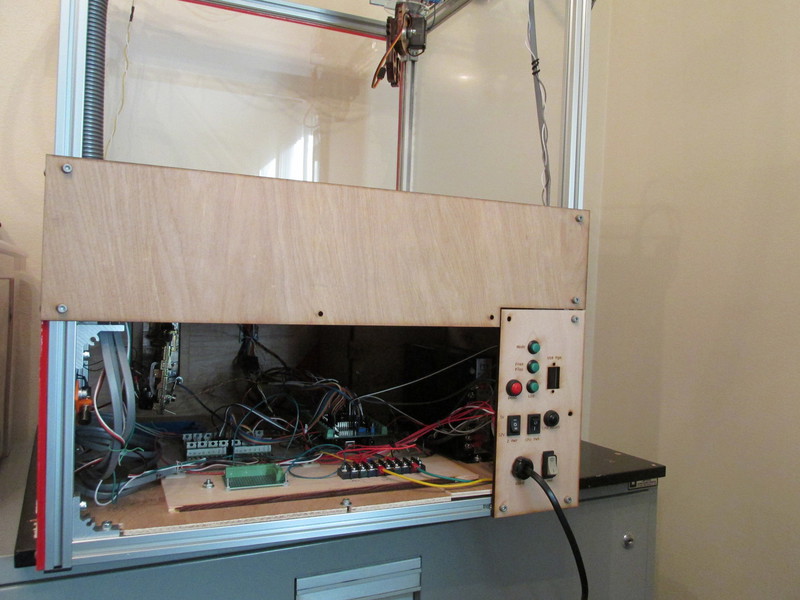
Revision changes for beta build: I keep flip-flopping regarding if I want to put a cap on the top of the machine or leave the gantry open. If the cap looks fugly, then it will be scrapped. Pictured below is what the cap might look like. I think.
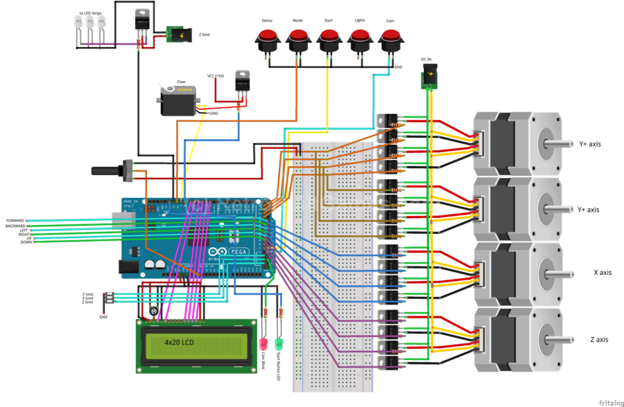
I also updated the wiring diagram. Might be helpful...
August 10, 2016: My thoughts and the future of kits.
When I approached this build it was more setting a goal for myself. I wanted to check-off all the boxes for features and flexibiltiy when I set out to make a claw machine. Now that it's complete I've had time to reflect on the BoM and it's feasibility. Simply put: it's not. The mini arcades are my bread and butter and they pay the bills. They also keep me busy and providing a claw machine kit of this complexity cannot be done with my resources. I will contine to add documentation for version 3 for those who want to build it on their own.
"So you've given up on a claw kit then?" Definately not. After stepping away from the project for a bit I was able see new light on how fix this complexity/ feasibility problem. Claw Machine ver4 is already being built. Taking a page from Nintendo's way to name newer product iterations in the same family, I am calling version 4 New Claw Machine until I think of something better. Maybe Claw Machine 4N? I am overflowing with original ideas.
I will not be showing it until it's up and running and near finalization. It will not take nearly the time to get to final like previous.
So how is progress with New Claw Machine you ask?
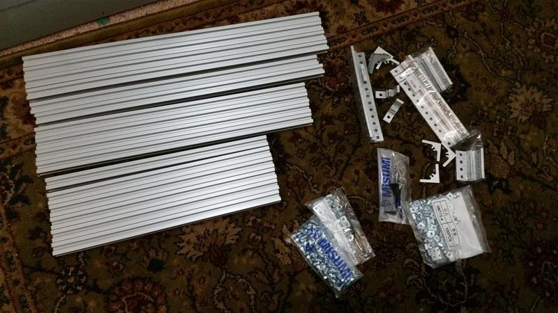
Better than expected. I've been working on it for ~two weeks (about four solid work days of dedicated time). The body/frame design is done and is comprised of all wood. No costly aluminum
bones. The body is more compact with closer proportions to a real claw machine footprint. It is about 20% smaller than machine ver3. The gantry is getting overhauled with linear bearings and 8mm
shafts. Think more 3D printer than CNC cutting machine like ver3 was derrivative of.This means less parts, simpler construction. Most of the time right now is feeling out the gantry and trying to
find the right balance of max gantry travel to hiding the gantry inside the body. This is challenging but I'm happy with how things are turning out.
Software will remain the same: Two game modes, demo button and usual switches for power. I will be adding an "input test mode" switch. I recall building ver 2 and 3 which was a pain to confirm all the controls were wired properly without a "test" mode. I had to have all the steppers connected [correctly] and powered until I could test the input controls. And I still had to flick the coin switch (so the machine would enter 'game mode') just to test functionality.
August 10, 2016 (earlier in the day):
Claw Machine Version 3 is complete! It has been for a few months ;) The biggest changes were a gantry update: new gantry cross-section is 20x40mm not 30x30mm. Bullet list of what those changes are:
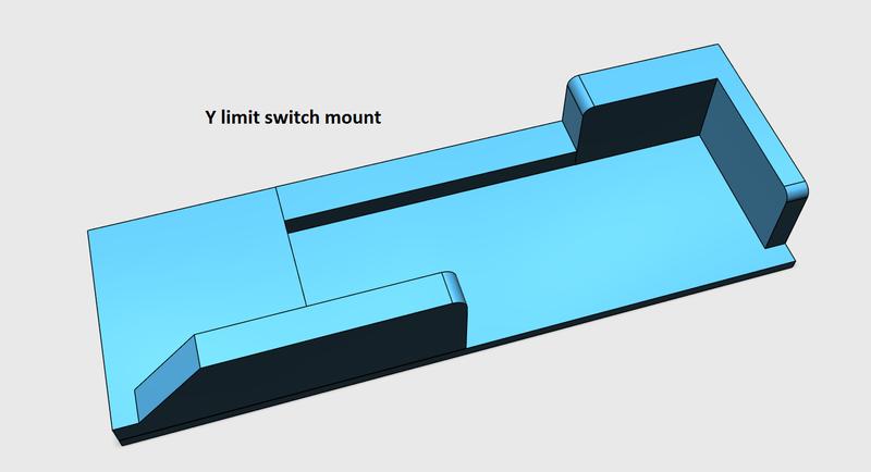
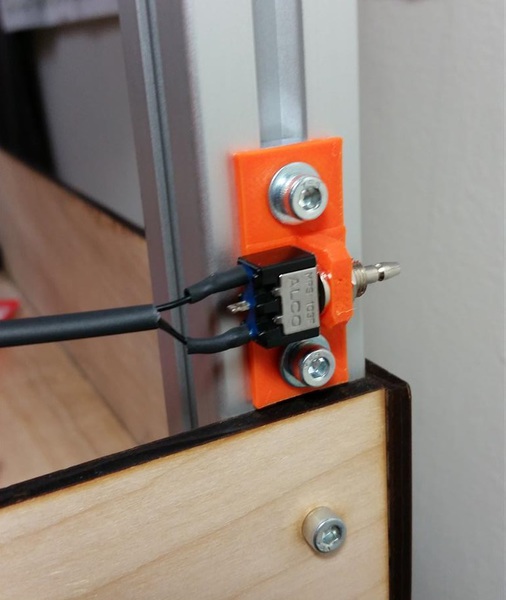
- Both the X and Y limit switch brackets were redesigned and moved.
- The 'simple' claw was put in place of the parallel claw as it tested better with players.
- The spacing for the X gantry belt loop was adjusted and fine tuned. This was a pain in the ass as I should have picked a standard belt size and design around it. But I did the opposite which required lots of tweaking to find that sweet spot for tension.
- Encased the machine in plexiglass. $40 worth.... Didn't realize the area was so large to cover
- Made a bunch of 3d printed brackets for the slimmer gantry design
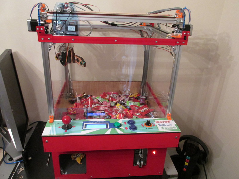
Ver 3 pics are below:


March 23, 2016:
Version 3 is near complete! Changes include the motor driver PCB I made, 'cleaner' wiring and slightly improved code. Also significant is improved gantry design for ver3. Gantry is less bulky, center of gravity is, well, more centered and overall look fits the machine better. It still needs a few tweaks to get the GT2 belt to fit properly. Powering the machine is a very useful replacement JAMMA PSU. The JAMMA PSU outputs 5V and 12V which is perfect for this machine. In an effort to save time (and avoid painting) I wrapped the wood body panels in red vinyl to give the machine some color. I also tried covering the aluminum rails with acrylic trim. I came across a pile of scrap 0.22 in thick red acrylic, which is what I used, but from a close inspection 0.125" thick trim would be better here.
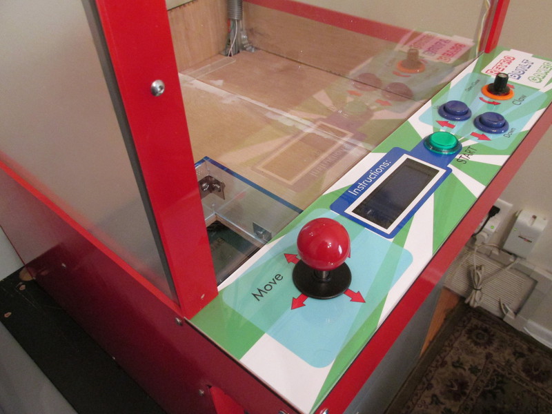
I found a volume knob from a scrapped Roland keyboard, which looks a bit better for the claw control knob. About 1/2 of people think the claw control is a button, so here's hoping the knob looks more like a knob. I also changed the graphics just slightly. The "Instructions" and Start button now are connected by a blue graphic blob. I hope that draws the eyes to both at the same time. Maybe? I have no idea if that will be the effect.
I added a demo button:) Because I can. The demo button picks a random number for the X and Y from a calibrated range, the gantry moves and the claw drops, closes, then returns to home. When you have a claw machine and all you want to do is eat the candy prizes, I let the demo button decide my fate.
The Y-axis limit switch was moved to the inside of the body (it was on the outside, but with it now enclosed in plastic, critial parts (like limit switches) on the outside was not a good idea.
Per everyone's request I have enclosed the play area in clear acrylic. The sides appear frosted, but that is because I have not removed the protective coating yet (still some work to be done on the machine - it gets moved constantly). The rear clear panel will be on a piano hinge for easy access.
I have begun the first round of ordering parts for kits. I still need to wire the LEDs that light the play area. After that, fine tune the body trim and that's it.
Quick Facts:
Footprint: 30 x 20.5 x 22inches (HxWxD)
Weight: ~30lbs
How long it took to build this version ~50hrs. Much faster compared to the first two versions as most of the design work is done. Wiring still takes about 2/3 of that time.
I am very pleased with this version. One nice feature is when the machine and I travel, the gantry will fit inside the body of the machine. Hence the reason the machine is two inches deeper than version2. When the gantry is layed diagonally on the prize floor it fits perfectly. This reduces the center of mass which avoids tipping when braking in my car. I tipped ver2 pretty hard once while driving these dang Pittsburgh hills. Storing the gantry inside also reduces the height of the machine from 30in to 26.5in. The hatchback of my jeep has a clearance of 27inches; yes this was the main factor for this feature.


There is also an added feature (because I can) aptly named demo/attract mode. The claw will pick a random X then Y number for position and try to pick something up.
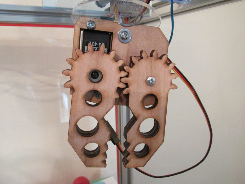
 New Claw design
Jan 2016 Update:
I have been trying a new claw design... I think I might scrap it. it's overly complicated and does not yeild the results I need. Off to the drawing board to simplify things.
There is nothing wrong with the current claw, but I would prefer a 3-finger claw, something that looks and plays closer to traditional claw machines. Building a 3 finger claw to this scale is stupid difficult for some reason. I really want it for the luck game mode, as when the claw drops, the 2 finger grabber just falls over. The three finger claw should stand upright when it is the dropped. That is the main motivation.
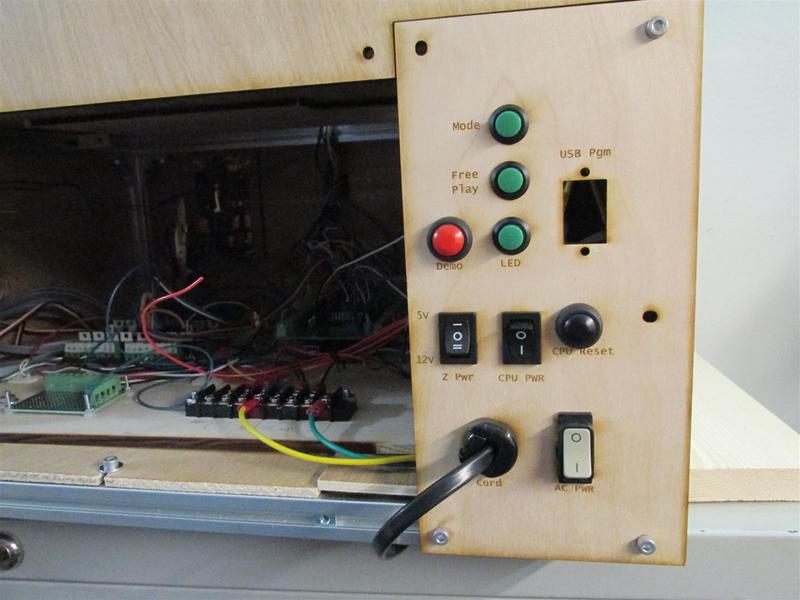
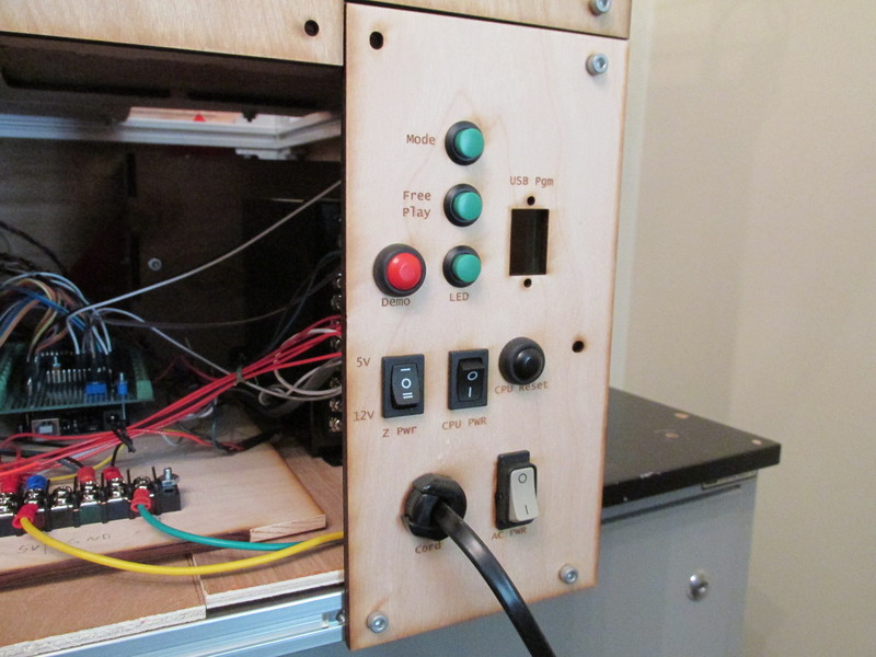
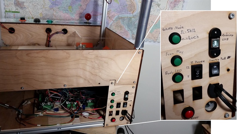
Two Game Modes
The machine also has a new control panel on the back! The previous one needed to be cleaned up. One notable difference is the 'Game Mode' button. Yes, the machine has two modes of play now! Default mode is the skill game where you get full control. The toggled mode is the game mode "luck" or how most traditional machines play; move to a location, drop the claw and hope for the best. It was on my secret list of 'things to do'. Now it's done :)
I also wrapped/bundled the gantry wires for protection and a cleaner appearance. I wanted to do a cable carrier tray, but I will save that for V3.
Photos of the new rear-panel are down in the main gallery.
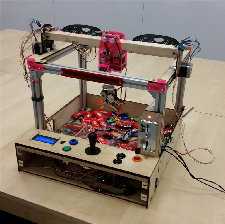
Version 2.0 Update! October 2015
I've been working on the newer claw machine design.

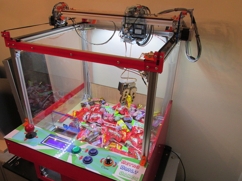
WHAT IS IT?
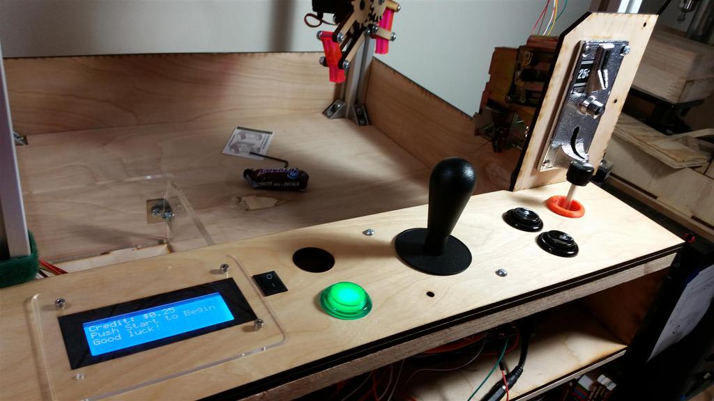
The DIY claw machine! Footprint is 20x26x19 inches, made from aluminum extrusion, custom laser cut acrylic/wood, stepper motors( nema17) and an Arduino Mega. The stepper driver is an all original design , built from scratch. No cheating with 3D printer motor drivers (nothing against them). Everything is custom designed, from the XZY gantry, to the claw, to the game logic. Stepper motors move the gantry, and a servo motor controls the claw (giving the claw an analog grip, not just open/close). Some parts are sourced from the plentiful DIY 3D printer market, other parts I had to make from scratch.
The Arduino code is all original too. The claw machine functions just like traditional claw machines in arcades, except my machine gives you more control and fairness. The
game is based on a timer (there is an LCD indicating how much time is left) which is set to 55seconds. Insert a quarter (can be set to free-play), and press start. You have 55 seconds to move and
position the claw, grab a prize, return it to the "prize chute" and go for more. Once time runs out the claw closes, the gantry moves back to the 'home position' and the claw then opens dropping
anything it might be carrying. Unlike the traditional Arcade claw machines, my DIY version gives you full control over this claw in the X,Y,Z axis and the claw grip itself. The only restriction is
time. Personally, the game is more fun since it's based less on one-time spatial judgment and more about motor skills and planning the best route for multiple prizes.
BACKGROUND
I started this project back in 2012 (see the videos below). These proof-of-concept builds were long before I was a Techshop member or really invested the proper commitment to a project. Without having access to real tools and working fulltime, I abandoned this project in 2012 due to the feeling it would never meet the expectations I envisioned for it.
I am pleased to say I revisited the claw machine in May 2015 and have promised myself to complete it and bring it to any video game convention I vend at (your quarters are mine!). The machine is still aways from competition, but I will be posting major updates here and DIY info when the design solidifies. Maybe it will turn into a DIY Kit :)
TLDR: I attempted this once in 2012, but my skills didn't match my ambition. I had to wait until a Maker Space opened up in my area. A few years later I tried again with better results.
COST TO BUILD:
Right now this has cost me about $470in parts. I got the steppers from an eBay seller who sells refurb and rebuilt steppers (about $8 per stepper) and I must say the steppers are awesome. Each motor has a molex connector at the base making build/ disassemble simple. The Arduino Mega is a off-brand from DealExtreme (works just fine), and the Al extrusion came Misumi USA (cheaper than 80/20 brand). The cost is pretty high as I buy more than I need and prepare for mistakes (I killed a few ULN2803's and TIP120's already) . It might be better to build this from DC motors, but I went with Nema 17 steppers primarily for two reasons, Mounting them uses a standardized hole pattern, and building a controller for them might prove useful in later projects. This project is easier to replicate (think kit form) with standard parts- Nema Steppers fit this due to the 3D printer market, not to mention all the belts, pulleys and wheels are readily available 3D printer parts. I have saved a few $ by making my own claw, and brackets to form the XYZ gantry.
I should stress designing and building the claw was a chore, but well worth it considering the alternatives I tried. I bought (then returned) a few claws as I was thoroughly disappointed in their quality.
There are many parts out there for gantries (Inventables' Maker slide...etc) but building my own was cheaper and simpler as surprising as that sounds. I was loathing the task of replicating/ relying-on dimensioned parts from around the web in hopes that everything would "work", but soon gave up on that since just one error in any drawing prorogates into frustration after you bought said parts and they just don't fit right.
Things have been rather simple with the steppers as I have been sticking to 5mm bore. This 5mm seems to be the most common DIY 3D printer parts, which are everywhere on eBay for cheap.
TLDR Cost about $470 so far, built from mainly 3D printer parts and designs all from scratch.
DESIGN TRICKS
I had a few hurdles to overcome regarding the stepper motor and servo motors. They are always on, meaning when not in motion, they have holding torque, or current pumping into the motor to keep them in position. This propagates heat into the ULN2803 drivers (transistor arrays that drive stepper motors) and unfortunately these DIP packages are not cut out to dissipate that kind of heat (even when only driving the steppers at 5v). To fix this, I just write all the pins LOW when the motors are idle. This cuts down on heat tremendously. We can get away with this since we are not concerned with losing motor position. Since the gantry is driving motion in a rack/pinion method, there is no need for holding torque as all the loading force is transferred perpendicular to the direction of motion (or laterally onto the motor shaft). Unlike a CNC machine, there is no kick-back force that would cause a motor to lose position, nor any ill effect if a position is lost. Therefore the claw machine motors have no holding torque which cuts down on power/heat and defaults the motors into a idle state. Win/win. This was the plan in the beginning, not because I expected heat in the ULN2803 to be an issue, but I wanted to be able to scale the gantry to a bigger and bigger machine. Having the stepper motors both holding their position while fighting gravity with a heavier gantry would be a sure way to fail early. I built claw machine version 1.0 using ULN2803s, but I later realized TIP120s where the right way to go. Version 2.0 was built using TIP120 Darling Transistor arrays (16 in total). These TIP120s can handle 3A continuous and up to 5A peak. They are much more robust to handle current, and with these, the machine can scale larger, handling more power (12v) and larger loads. I did end up making a custom PCB for these transistors. Well worth it if you find yourself building more than one claw machine, also it just makes wiring so much cleaner and organized inside the machine. The servo motor (motor that drives the claw) also had the same behavior. Power is always being driven into the servo in order to hold the claw position. This is an issue when the game is in idle (not being played) as the servo motor heats up significantly and will reduce its life space. I looked everywhere and despite every claim to saying it will work, you cannot simply call the function "servo.detach(pin#) in Arduino. This would in theory detach the communication signal to the servo, but most servos are not designed to experience a 'null' communication. It's an undefined state. Needless to say the "detach" command does not work. The way around this was to just connect the servo power line to a transistor and shut it off (with logic) when the claw game is not in play. Used a TIP120 for this.
TLDR: Use TIP120s to handle stepper motor current, and disable hold torque in code and servo power when game is in idle.

How To Build:
Materials
Let me first say there are many ways to build this claw machine. I found that making a hybrid CNC/ 3D printer machine makes things simpler mechanically, as these parts are readily available, cheap, and more modular as they are marketed to build a variety of machines. You could definitely go the tradition claw machine route using DC motors for the gantry, which simplifies the power electronics (H bridge ICs) and code to drive them; however, the trade off is it complicates the drive mechanics. Most claw machines are have worm gears that drive the gantry, giving the speed reduction and required torque. I prefer a 'bolt-on' approach rather than a custom fabricated mini version for the gantry. I found stepper motors are crazy easy to mount, have a good range in speed (on the low end of speed), and provide more torque than I need (think scalability), so this route was chosen.
COST TO BUILD:
I included a modified Bill of Materials for this machine. The BoM reflects the machine documented here. The total cost is $470. The crossed out items in the BoM reflect the reduced cost version. This removes all the Aluminum extrusion (in place of a wood frame) and some other non-necessities like the LCD and mechanical coin acceptor; reducing the cost to about $210.
I did not expect this machine to cost so much. On the bright side, with a quarter slot it can pay for itself over time and even become profitable. So let's call this build an 'investment'
WHERE TO BUY PARTS:
eBay. If you can wait for things to ship from China, you can't beat those ebay prices.
WHY DID YOU USE ____ PART?
I got the steppers from a USA eBay seller who sells refurb and rebuilt steppers (about $8 per stepper) and I must say the steppers are awesome. Each motor has a molex connector at the base making build/ disassemble simple. The Arduino Mega is a off-brand from DealExtreme (works just fine), and the Al extrusion came Misumi USA (cheaper than 80/20 brand). The cost is pretty high as I buy more than I need and prepare for mistakes (I killed a few ULN2803's and TIP120's already) . It might be better to build this from DC motors, but I went with Nema 17 steppers primarily for two reasons, Mounting them uses a standardized hole pattern, and building a controller for them might prove useful in later projects. This project is easier to replicate (think kit form) with standard parts- Nema Steppers fit this due to the 3D printer market, not to mention all the belts, pulleys and wheels are readily available 3D printer parts. I have saved a few $ by making my own claw, and brackets to form the XYZ gantry. I should stress designing and building the claw was a chore, but well worth it considering the alternatives I tried. I bought (then returned) a few claws as I was thoroughly disappointed in their quality. There are many parts out there for gantries (Inventables' Maker slide...etc) but building my own was cheaper and simpler as surprising as that sounds. I was loathing the task of replicating/ relying-on dimensioned parts from around the web in hopes that everything would "work", but soon gave up on that since just one error in any drawing propagates into frustration after you bought said parts and they just don't fit right. Things have been rather simple with the steppers as I have been sticking to 5mm bore. This 5mm seems to be the most common DIY 3D printer parts, which are everywhere on eBay for cheap.
TL:DR Cost=$470 using Al extrusion for frame, built from 3D printer parts and custom designs from scratch. Total cost is ~$210 if you build the frame from wood.


Frame
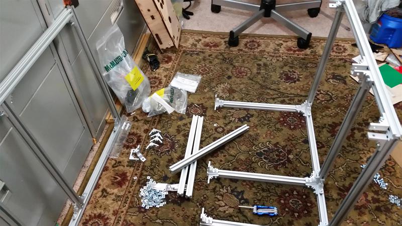
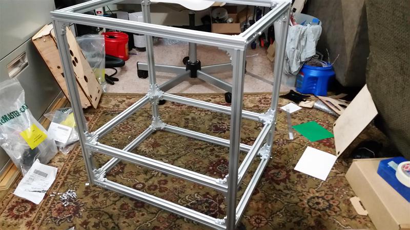
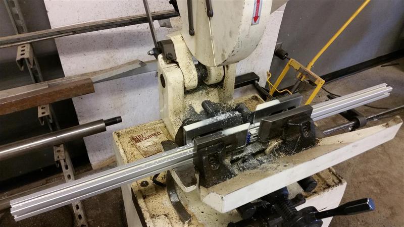
This is a AEX frame kit from MisumiUSA. Just specify the dimensions and you get everything pre-cut with all the hardware to build the frame. Sure it's a bit more costly, but the alternative was buying the raw extrusion in longer stock, cutting each one on the cold-saw, deburring each cut, cleaning the coolant off each cut, and messing up at least one cut because that's just how I operate.
I did have to buy long stock for the gantry beam and cut that myself (it's 20.25" long in my claw). If you don't have access to a cold saw (think metal miter saw with coolant pump) try to buy ypur extrusion from a place that cuts for you. The bigger the seller, the cheaper the custom cutting fee. Bandsaw works too.
I went with a slightly more- pre-fabbed frame and would do it again.
Frame assembly is rather straightforward. It does take some planning as it uses pre-insertion nuts.
Body
This thing was really about aesthetics. After putting a temporary body on it, I knew the direction I wanted to go with the body. This step took some time as I had to wait to get all the parts on hand, like the quarter acceptor before knowing where to place it.

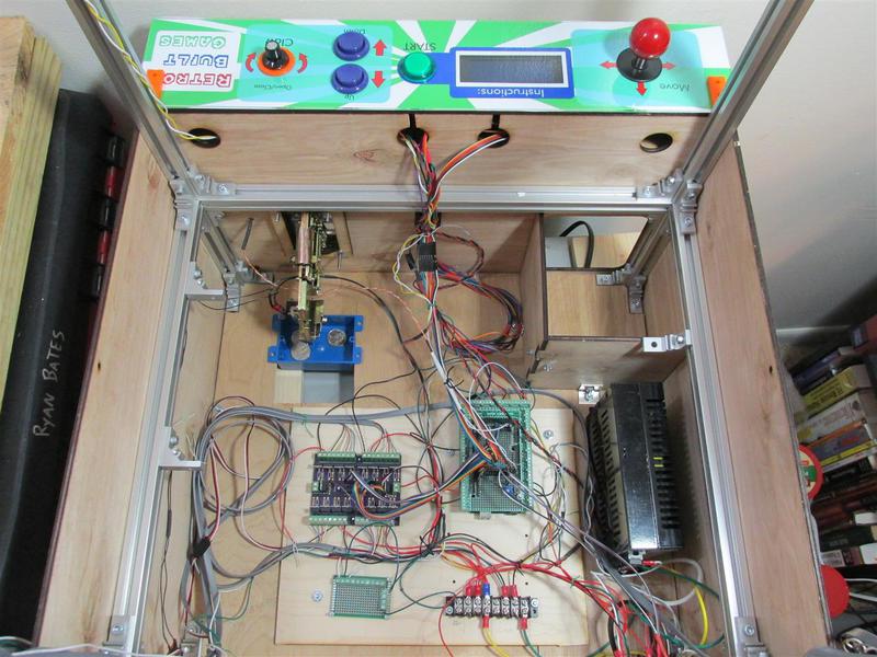
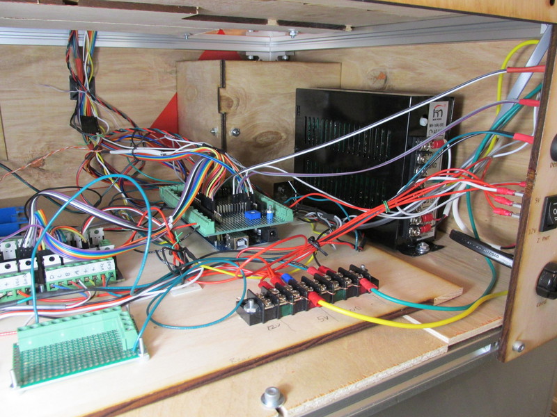
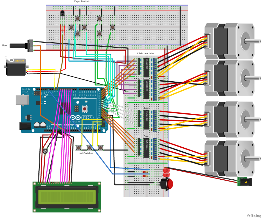
Electronics + Circuits
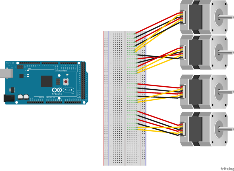
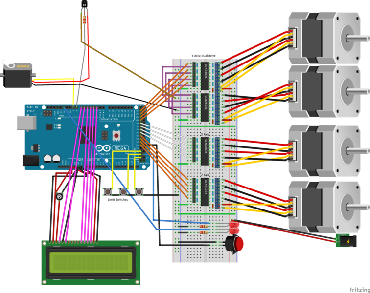
Schematics are great, but not everyone can read them. I opted to make a diagram with Fritzing. This also helps to see the 'big picture'. Here's the guts of the machine.
Let's break the circuit down into chunks.
First wire the stepper motors. Note that the Y axis has two motors on each side, they are wired mirror to each other so the unipolar motors move in tandem.
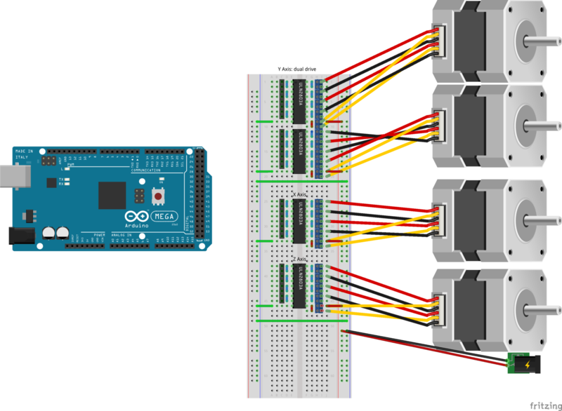
1. Add the power transistors. In actuality I used TIP120s not ULN2803s, but schematically it's all the same.
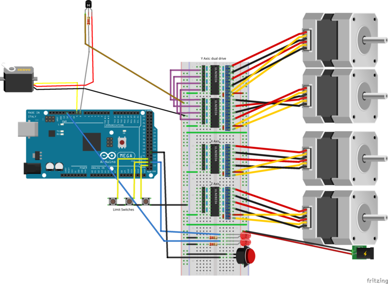
2. Wire servo motor, limit switches, status LEDS, coin trigger switch and power to steppers.
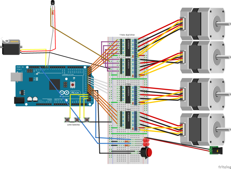
3. Wire stepper transistor TTL to Arduino.
4. Connect LCD (having LCD displaying game instructions is optional, but nice)
5. Wire player controls. This is what the player interfaces to control the gantry and claw. Remember the claw is using a potentiometer, but you could easily make it a button instead.

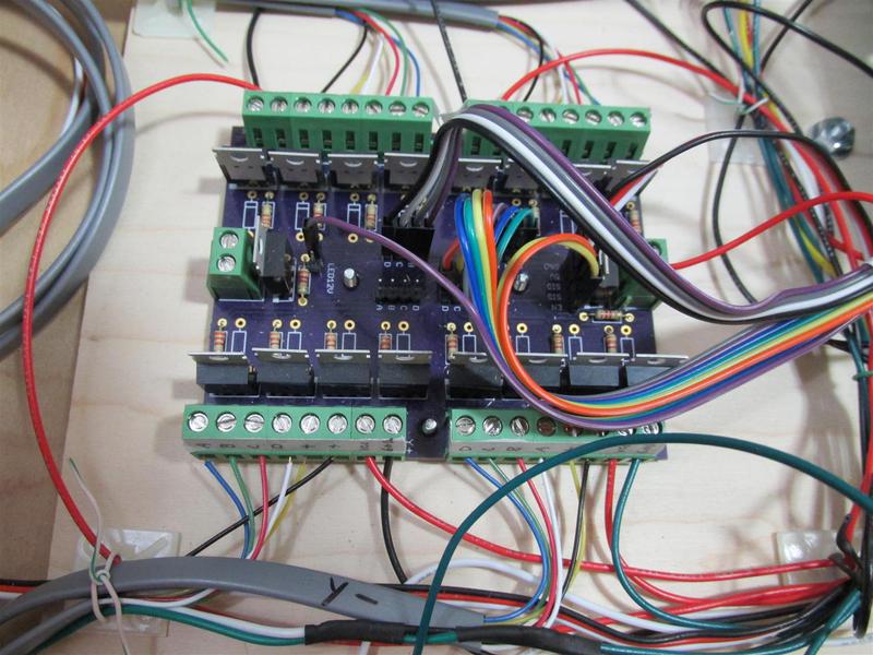
PCB (optional)
I built this circuit on plated perf boards, and it took about 4-5 hours. I laid out a board because I figured I would be building this claw machine again. The custom PCB makes the electronics steps faster, and much more organized. I used Eagle CAD to layout the board and had OSH Park fabricate the board. Fab costs are $10/sq inch, which will yield three PCBs (prototype price/quantity).
Whatever route you pick, take plenty of time to make your electronics clean. Mount your boards, secure psu, bundle wires, fasten to frame and make sure everything is accessible in case repairs are needed. Take consideration about how the TIP120 package will dissipate heat (heatsink, air cool, force air cool) if you decide to run things on 12V+.


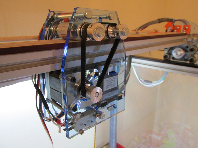
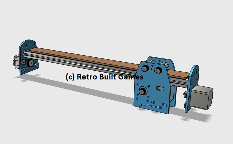
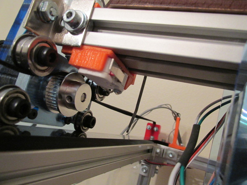
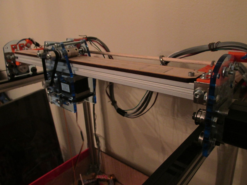
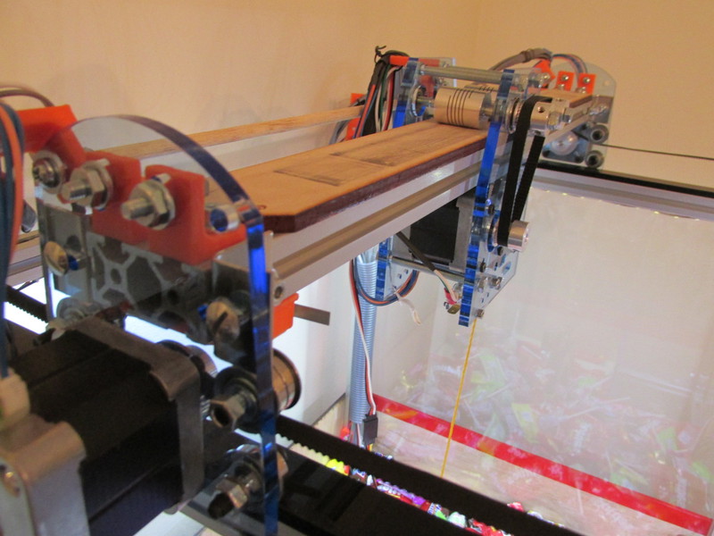
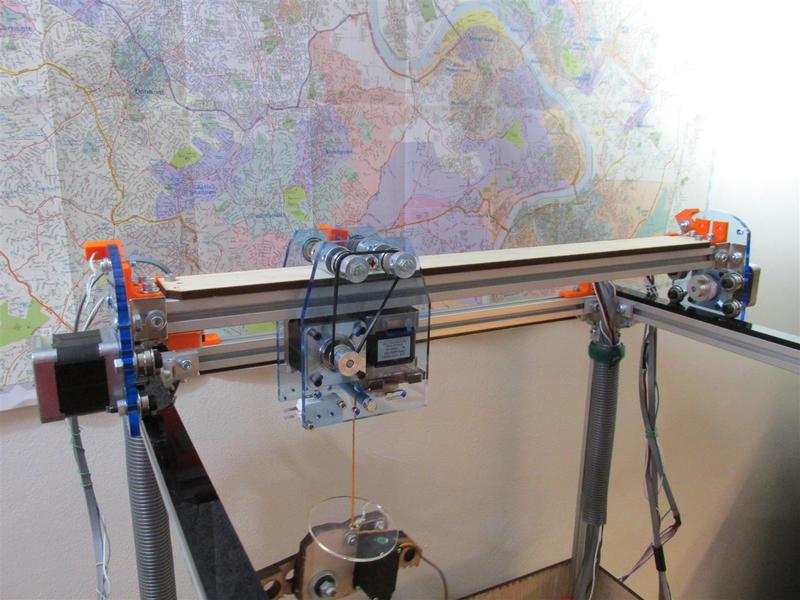
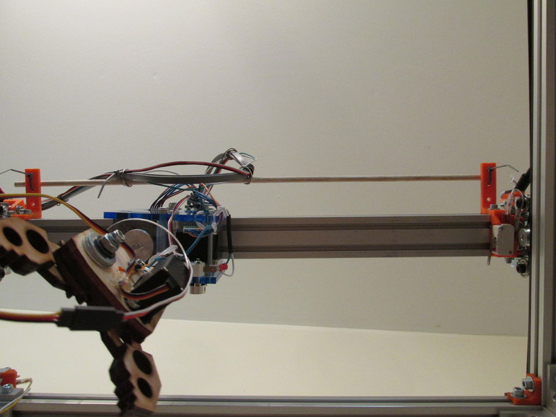
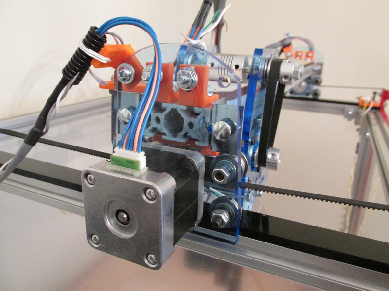
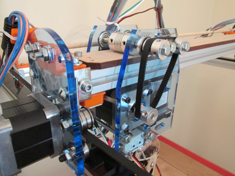
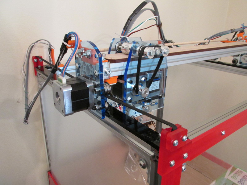
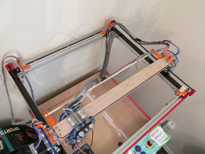
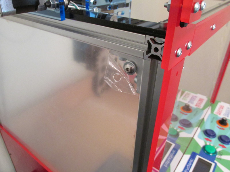
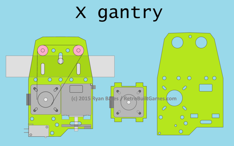
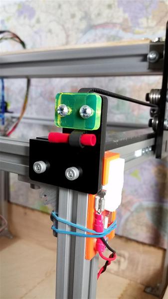
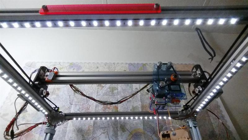
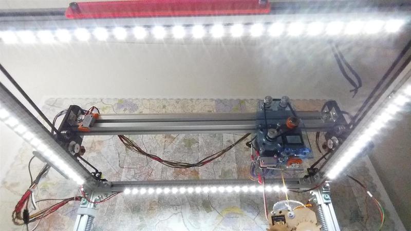
Gantry Design
The drawings and photos explain how the gantry is constructed. The stepper motors and their user-friendly mounting holes influence 80% of this design. There is no cheating this section. Measure every part, draw it to scale. The gantry went through the most revisions, about 7 or 8.
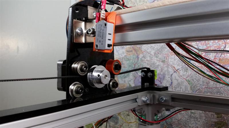
The 2 'rollers' on the X gantry are 5mm shaft couplers. Sure, that's not what they are made for, but they work well. I tried 3D printing solid cylinders and tapping them so they would lock to the driving axle, but the shaft couplers worked better imo.
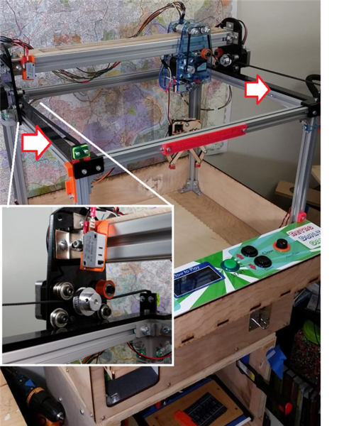
A very important design feature are the adjustable black rack rails the gantry rides on. The last photo points to these rails that can move in and out. These rails serve as the fudge factor compensator. This makes sure, that whatever the gantry width is (you only get so many chances to cut the aluminum) that we can make it work for our system. The rails can move in and out to fit the riding wheels (flanged bearings). They also adjust in case the frame is out of square, though I did not have this problem with the Al frame. If you build machine with wood make sure everything is square!

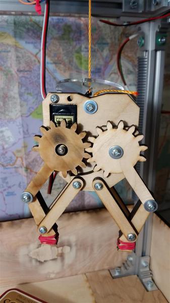
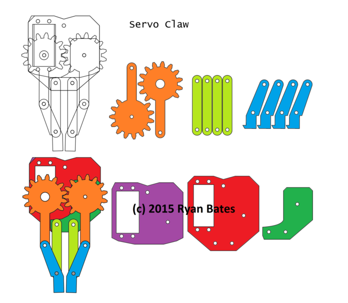
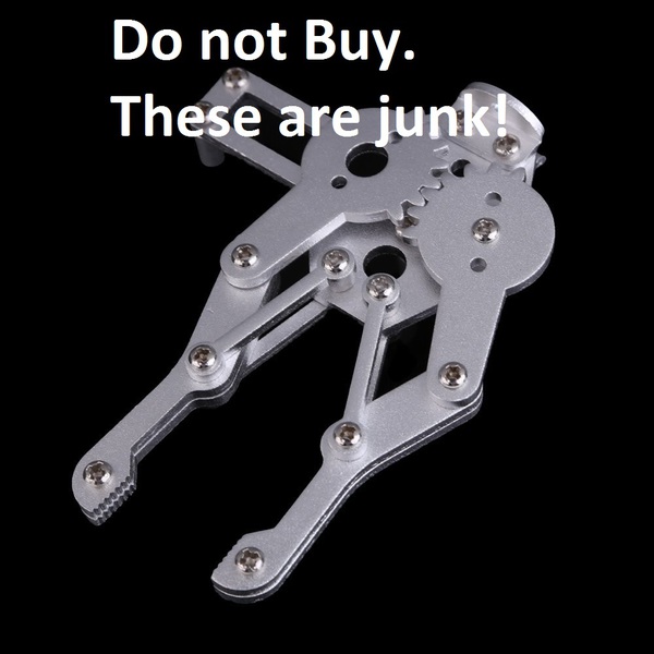
Claw Design
Initially I bought a claw, thinking I could save time. I bought some stamped metal claw off Amazon with high hopes. I've seen the same kind everywhere so I figured it was worth the $18....tolerances were sloppy, rivets were loose, it didn't even fit standard size servos. I returned it and turned to my drawing board. This took a few weeks of testing and revising, but I made a claw of similar cantilever design that fits most generic servo motors. Key here is to use nylon lock washers so the claw does not disassemble itself after repeated use. I am very happy with the strength. I did add rubber bands to help with grip. Some candy packaging is rather slippery; the rubber bands add some friction (Twisters I am looking at you). The claw is made from 0.25" plywood, which keeps it light. Servo motor is 180 degree.
A number of people ask me, can you attached a standard claw to this? Yes. Although those claws use solenoids that need 50V and a few amps to drive them; knowing that interfacing them with this machine is simple. My claw runs off a medium sized 5V and 12V dual power supply. It was actually a PSU for a external CD-ROM drive. These are inexpensive (I actually found mine in the garbage). If you want to use a real amusement type claw, you'll need to drive it with the appropriate power (voltage + current) and this might add some unexpected cost. However you will get props in the cool factor.

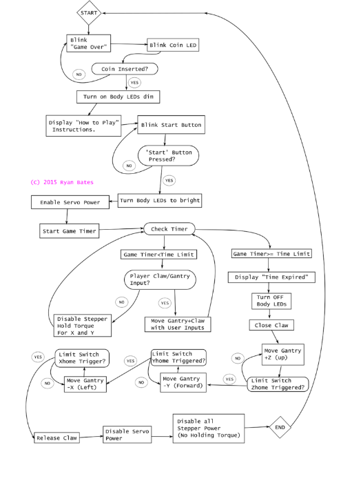
Game Design/ Logic Flow
If you're going to write any code/ program. It is best to have a map. The diagram above shows how the game flows and highlights specific behaviors of my claw machine. (Of course I didnt make this before I started coding. Who does that?) Over a two week period I wrote most of the code. I tackled small chuncks at a time and only when 'feature creep' started to find it's way into my brain ("Oh these lights should blink twice and then the pize chute should have lights and there should be two game modes....."), did I have to pull back and layout what does what.
Code
The below diagram shows what the provided code does. If you want your machine to "go home", blink lights and have a more traditional behavior, you'll need to code this yourself. Trust me, it's for your own good.

Download the code:
Microsoft Word document [14.9 KB]
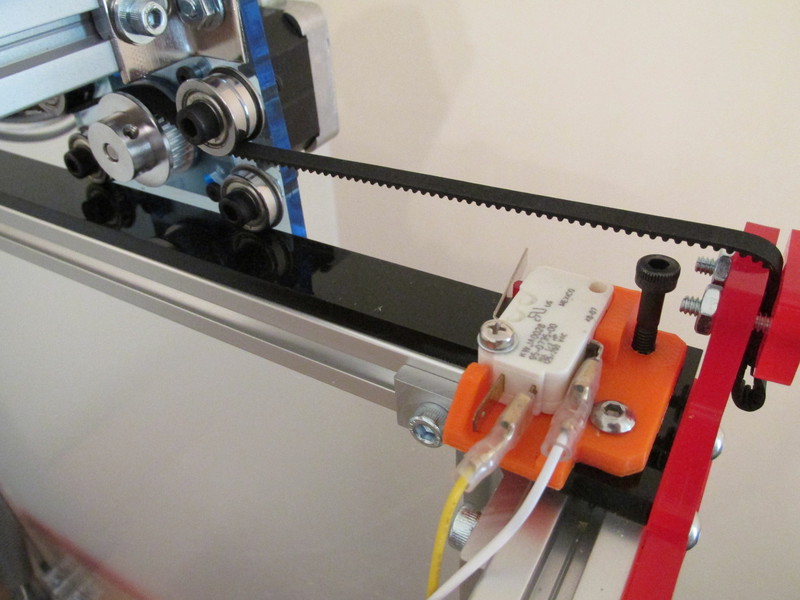
Custom Parts + Features
There are a few brackets and mounts that just can't be cut from 2D stock. Here are some brackets that I made to fit standard arcade microswitches. I made these brackets on a PrintrBot Simple Metal. I think it's a very good machine btw. These brackets+microswitches are now the limit switches on the machine.
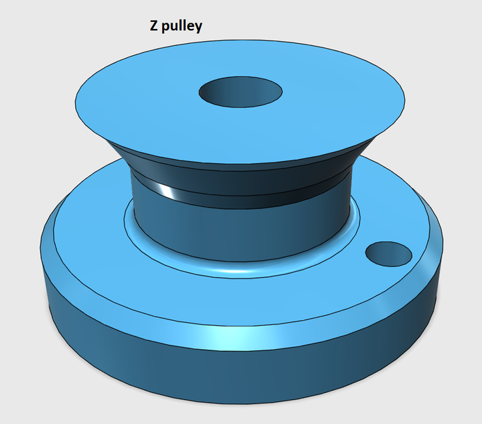
A pulley was made to increase the diameter of the Z shaft. A larger diameter will wind (pull up) the claw faster. "Why not just increase the stepper rotation speed?" I tried this. Driving the stepper close to it's max velocity will result in loss of torque+skip steps when under load.
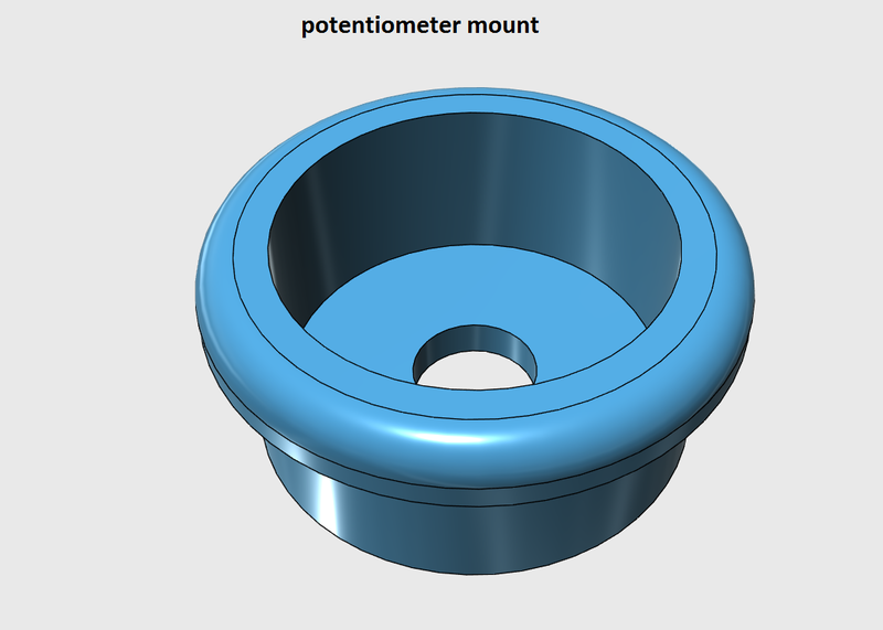
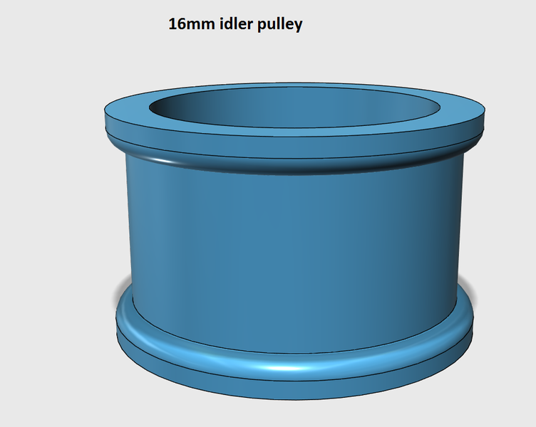
I also had to make a mount for my potentiometer (claw control) and some other brackets to mount buttons and take up slack in the GT2 belts.


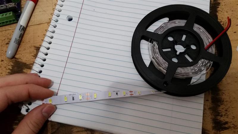
Lights
I attached 12V LED light strips to the underside of the gantry to give some light to the game. They are controlled via PWM with a TIP120. By now these SMD LED strips are rather common on eBay, but their effectiveness is not to be understated. Aside from making the pile of mixed candy look more appealing and illuminating the playfield, these LEDs also give visual cues for the claw game. The body LEDs turn off when the game is idle or transitions to game over, turn dim when a quarter is inserted, go full brightness when the game is being played, and flash when "time expired" is displayed.
Done!
I think I have about 80-100 hours built in claw machine v2. I am very pleased with it. Total time with building, wiring, designing (2D + 3D CAD, PCB layout) for both v1 and 2 machine it likely near 300 hours. Well worth it.
Version 2.0 Claw Machine
Things I wanted to improve from v1.0:
- Replace the wood beam used in the gantry with more aluminum extrusion. DONE
- Close-off the control panel, and remove a button hole. DONE
- Layout a PCB for the driver circuit. DONE !!!!
- Rebuild the X gantry with a smaller belt. DONE
- Make a video covering the complete assembly. SORTA DONE
- Maybe redesign the driver circuit to handle 3A peak (2A continuous) for super size machine versions. DONE
- Add LEDS to light the play area when active. DONE
- Install Limit Switches and program "go to home" at gameover. DONE
- Paint/artwork the entire thing. PROBABLY WILL NEVER BE DONE
- Incase machine in clear acrylic to stop cheaters. Will do onVer 3
- Add 2nd game mode: Luck or Skill mode toggle switch. DONE Jan 2016
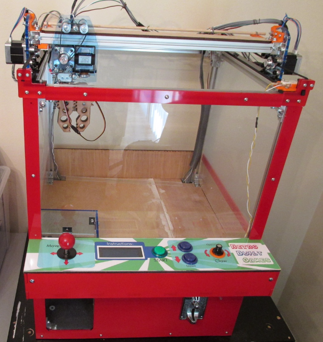
I really like how this new design turned out. The biggest changes were: layout of the control panel (putting the screen in the center), taller machine to allow for a gravity fed prize chute, and "return to home" function when the game ends.
I also added LED lights that shine down on the play area which act as visual cues for the game's start and end. The light flash when time expires.
I would like to make the frame just a little bit taller (about 2 inches) as the coin acceptor is a big crammed, but really I am very pleased with everything! The electronics have been beefed up to handle more power if needed. I did add a secret switch on the back that can switch the power given to the z motor from 5V to 12V. This boots the lifting power from ~6oz to ~3lbs.
It is important to note how my game design influences and conditions behavior. My machine most definitely reconditions the perception of this "skill game" versus traditional claw machines. Let's talk some background first.
TRADITIONAL MACHINE OPERATION
Traditional commercial claw machines are designed to be profitable all the time. They have dip switches that adjust the "payout rate". Meaning if set to say, 1:5, then after four plays or payments, only will the 5th play result the ability to successfully redeem a prize. When I say 'ability' only now will skill be a factor, as odds are still stacked against the player and their ability to grab something. It's only on the payout attempt when the claw will actually be given the correct strength to pick something up; the rest lays in the players skill to position it. Other machines allow the strength of the claw to be adjusted for the payout rate, either for all play attempts or only on the payout rate. If you hang around a claw machine you can tally the payout rate and with some luck, rake in the prizes. Of course narrowing that payout ratio helps if when it does comes up, the player is a skilled at the claw machine. Modern machines randomize the payout rate, so even if you observe the machine all day in the hands of a skilled operator, it's not likey you'll know when the next "winning state" is coming up.
PROFITABILITY RATIO
Lastly all machines have two counters in them. This is the business end of the machine. Simple numeric counters that track how many payments have been made, and how many prizes were given out. Good or 'fair' machine owners [hopefully] look at this ratio and choose to adjust the machine so it's either fair or profitable. Ideally of mix of both so people come back to play the machine. Depending on what they set this at, you're experience will vary. Do note some never look at this at all, and just look at the money inside the hopper at the end of the week. Image being the owner of one of these machines and you just bought it. You've spend ~$3,000 on a new machine and you want to see a turn around, in the short term. Commonly, most owners of a newer machine will have a more aggressive approach profitability. Older machines that have essentially paid for themselves (or owners that look to make up the purchase in the long term) are more likely to be easier to win based on this owner mentality. Of course all this is not taking account of other machines (or they of business) that effect the overall profitability of the store, we are just focusing on the isolated economy of one machine. You can be sure if a machine has an iPhone or something ridiculously expensive inside, the payout ratio is either very low and/or it is nearly impossible to pickup said item with the mechanics of the claw design. This is the exact same principle behind the games that have an PS4 dangling from a tiny string. Both the high ticket item, and cost of the machine need to be profitable (long term /short term) before a prize is dispensed.
REWARD SKILL NOT LUCK
I feel it is clearly the design of the game: that being "full control" of the machine for the allotted time, that justifies the payment in the customer's perspective. That justification is also influenced by the following observations people made when approaching the machine: 1) People saw others winning candy, 2) People saw players make multiple attempts to grab candy showcasing "this game is different".
I had many individuals ask "is this machine rigged like the others?" or something similar. The stigma is clear. But with this full control design, the stigma changes.
If you lose, the take away is: the player is most likely to blame for failure, not the machine. I heard many kids says "I beat the game". The feeling of winning against a fair challenge is what makes this fun. And it's the knowledge that you can win, with your abilities, that makes a game fun and for the owner, profitable for the long term. The game rewards skill not luck.
INTERNAL BATTLES
The most interesting observation came from those who lost. Around 50% of those who lost the player would have candy in the claw, but "that's not the kind I like" resulting in dropping this piece and trying to grab something else and subsequently running out time before a new piece is grabbed. Especially in this case, the player is to blame, and it makes for an interesting mix of emotions as they walk away contemplating what life lesson to learn from this experience.
July 2015
Below is "version 1.0" of this claw machine build.
List of parts I used and costs.
Claw Machine v1 BoM.pdf
Adobe Acrobat document [211.2 KB]
 Basic circuit for claw machine.
Below are some early builds I did for the claw machine.


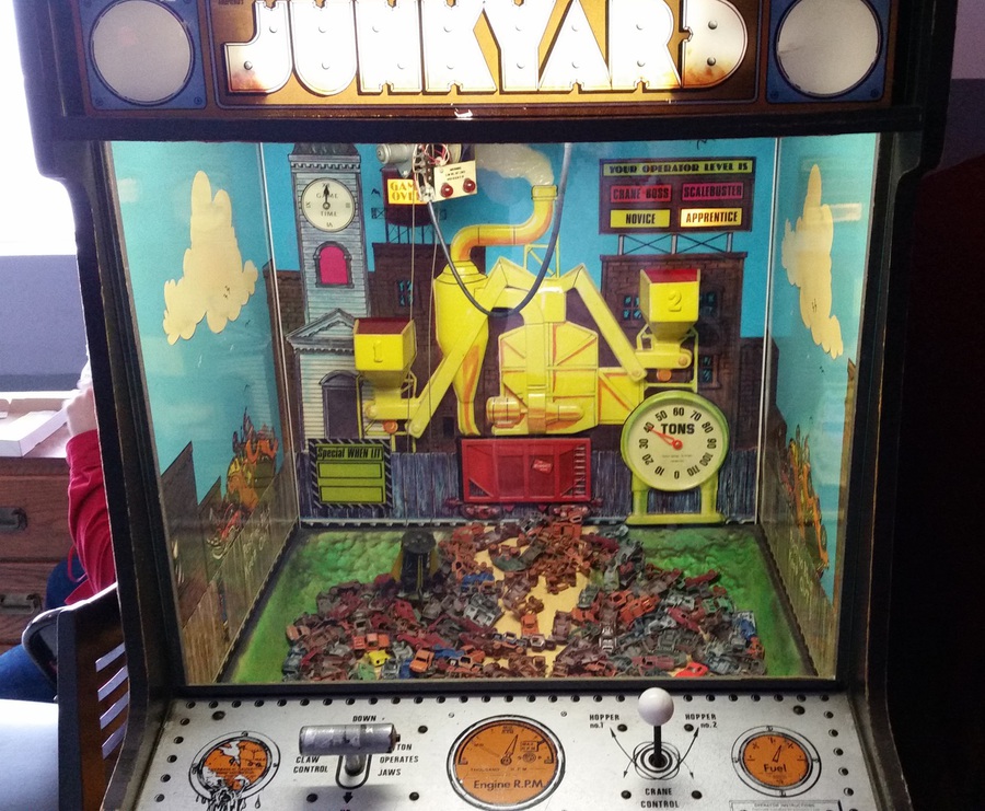 Classic Claw game from 1960s. Full control games are no longer trendy.
© 2013-2023 Ryan Bates and © 2013-2023 Retro Built Games, LLC. All photos, designs, documents, and graphics (C) Ryan Bates. All Rights Reserved.
This site is best viewed on a desktop PC. Raspberry Pi is a trademark of the Raspberry Pi Foundation. ARDUINO® and other Arduino brands and logos published in the website are Trademarks of Arduino AG.