DIY Coin Pusher
Buy the vector files here on my esty shop.
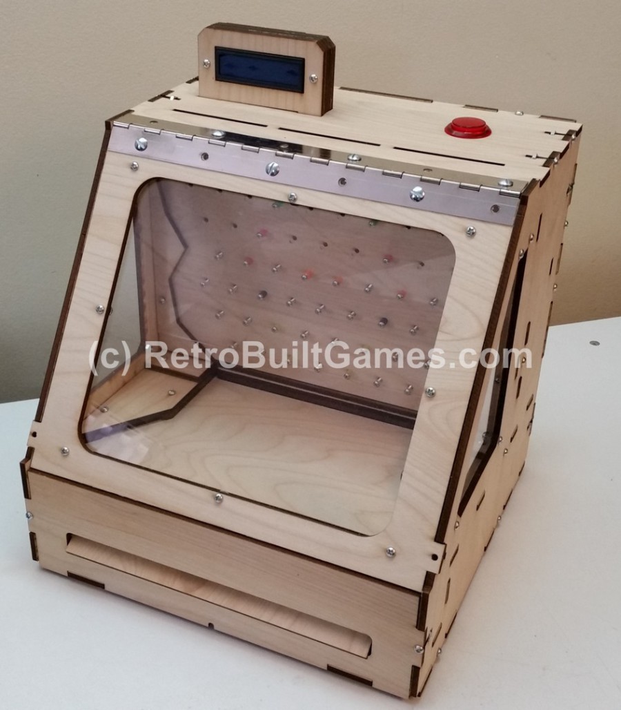
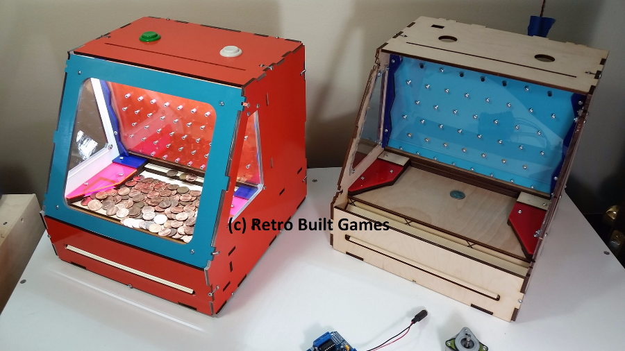
You're looking at the revised Coin Pusher. This is version two which addressed some deficiencies in the initial release. First off, now you can pick how you want to drive the coin dozer. There are three options: hand crank, standard size servo, stepper motor. Other 'features':
1) The front was redesigned to accommodate a continuous hinge. And finally a section on top allow for the easy install of a LCD screen.
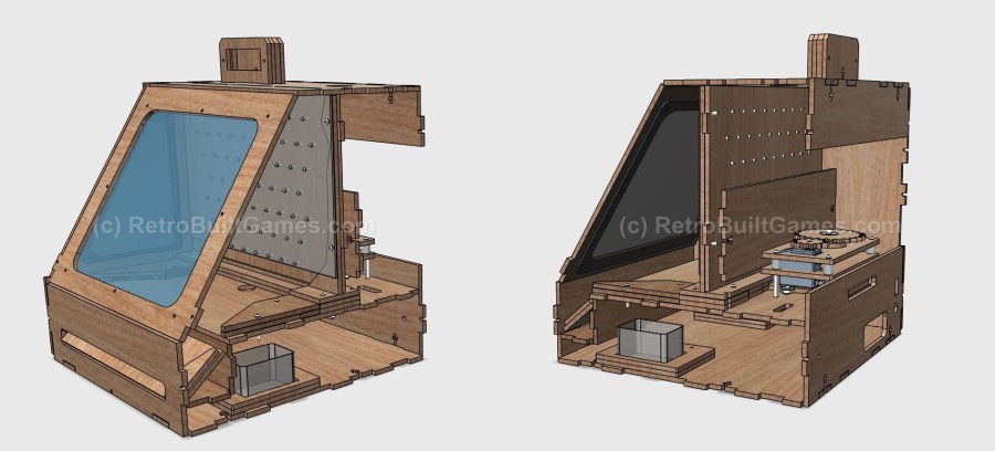
2) There are now cavities under the coin floor that capture and hold coins won by the 'house' slots. No more loose coins shifting around where electronics are mounted.
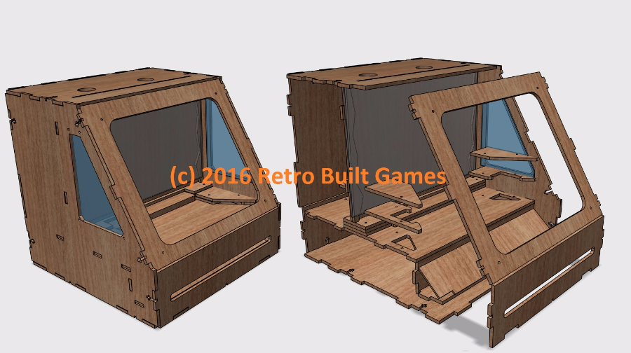
3) More captive nut points where added to the inner body frame. This helps pull the side panel in and stiffens of the body.
4) Coin 'plinko' area was fixed to prevent coins from getting stuck on the outer left and right sides.
5) The overall footprint was reduced by 0.75" making it fit in standard boxes.
6) Rewrote code to use interrupts and drive servo.
How to Assemble
 Coin Pusher V2

Hardware description and quantities
Coin Pusher BoM V2 Mechanical Hardware.p[...]
Adobe Acrobat document [415.2 KB]
LCD i2C library here: https://bitbucket.org/fmalpartida/new-liquidcrystal/downloads/
The LCD+backpack are optional hardware components.
This code uses an i2c backpack for the 2x16 LCD. Be sure to have the correct libraries for i2c in your Arduino app folder.
Coin_Pusher_v2.0_with_i2c_LCD_ISR.rar
Compressed file archive [2.0 KB]
Version 1 shown below (and has been discontinued).
In a never ending effort to build my own desktop arcade experience, I present the coin pusher. While the claw machine when back into the R&D phase to reduce complexity, I decided I could design a coin pusher in the interim. Here is it!

CODE for coin pusher version 1 (using above circuit).
/*Coin Pusher V0_2 by Ryan Bates (c) 2016 Retro Built Games
Features: Tilt sensor, Tilt LED, speed adjustment for stepper.
Basic operation to drive a UNIPOLAR stepper motor with a button and a ULN2803 (8 arrary darlington stepper)
Code will also work with four TIP120 darlington transistors. If using a Arduino Motor Sheild you'll have to modify this code.
*/
const int button3Shot = 11;
const int buttonSkill = 12;
const int led = 13;
const int tiltRelay = 8;
const int tiltSense = A5;
long timeout = 86400000; //~1 day in millis
int speedValue =0;
int potPin =A0;
long StepperRPM = 100; // default speed and hold variable
int buttonState3Shot = HIGH;
int buttonStateSkill = HIGH;
#include <Stepper.h>
const int stepsPerRevolution = 200; //
Stepper Ystepper(stepsPerRevolution, 2,3,4,5);
void setup() {
Serial.begin(9600);
pinMode(button3Shot, INPUT_PULLUP); //enable intermal pull ups. Note all functioning logic must trigger low.
pinMode(buttonSkill, INPUT_PULLUP);
pinMode(tiltSense, INPUT_PULLUP);
pinMode(tiltRelay, OUTPUT);
pinMode(led, OUTPUT);
digitalWrite(led,LOW);
digitalWrite(tiltRelay,HIGH);
}
void loop() {
speedValue = analogRead(potPin); //read the voltage at the potentiometer ( 0 - 5v)
//then convert this reading to the analog resolution number
(0-1023)
if (digitalRead(tiltSense)==LOW) { //if the tilt sensor is not connected, this IF statement will never trigger.
digitalWrite(led,HIGH);
digitalWrite(tiltRelay, LOW); // relay triggers on LOW
delay(1000); digitalWrite(tiltRelay, HIGH);
delay(1500); //this longer delay is to "wait out" the swinging plum blob. After a hard tilt,
//the plum bob will continue to swing and may continue to trigger the bell until dampened
delay(timeout); // essentially redering the machine out of service [tilt] until the reset button is pressed on the atmega
}
//----------Stepper Forward-----------------------------------------------------------------------------
Ystepper.setSpeed(speedValue/10 + 10); // will give a stepper speed range of ~10 RPM - 110 RPM. Max speed is ~120RPM. if you go beyond 120RPM, motor will skip steps
while ((digitalRead(buttonSkill)==LOW) && (digitalRead(tiltSense)==HIGH)) { //If button is pressed and tilt has not been activated, drive motor
//digitalWrite(led,HIGH); //when button is pressed (goes low) turn led on and move stepper 200 steps
Ystepper.step(10); //200 steps = 1 rotation
}
//----------Stepper Backward---------------------------------------------------------------------------
Ystepper.setSpeed(speedValue/10 + 10); //optional to have 2nd button or alternate motor drive profile
while (digitalRead(button3Shot) == LOW) {
digitalWrite(led,HIGH);
Ystepper.step(-600); //-200 steps = 1 rotation (opposite rotation)
}
digitalWrite(2,LOW); //disables hold (no current supplied to stepper when idle)
digitalWrite(3,LOW);
digitalWrite(4,LOW);
digitalWrite(5,LOW);
digitalWrite(led,LOW);
}
© 2013-2023 Ryan Bates and © 2013-2023 Retro Built Games, LLC. All photos, designs, documents, and graphics (C) Ryan Bates. All Rights Reserved.
This site is best viewed on a desktop PC. Raspberry Pi is a trademark of the Raspberry Pi Foundation. ARDUINO® and other Arduino brands and logos published in the website are Trademarks of Arduino AG.