Better Wiring with the Power Block
I've built enough arcades to know wiring them can be combersome. For those new to electronics it can be a daunting task. I made this this PCB to simplify getting power to the various electronic components (LCD, amplifier, backlight) while being versatile enough to be used in any small arcade build.

1) Power Switch and Setup
The power block distributes and controls power to the main parts of your arcade: LCD, amplifier, backlights, and raspberry pi. Power is controled by requiring a switch wired into the terminals (PCB) SW1 and SW2. If you don't have a switch, you can jumper the terminals (also indicated with a [ 'bracket' on the PCB). If you do not have a swtich jumper the SW1 terminal with a wire and also SW2 with another wire. Jumper them means power is also passed onto anything down stream of these connections.
For example the SW2 (LED) is down stream of SW1. If you turn off SW1 (remove the jumper) then you cut power to everything downstream and SW2's power connection to LED turns off: it doesn't matter if SW2 is still switched on (jumpered).
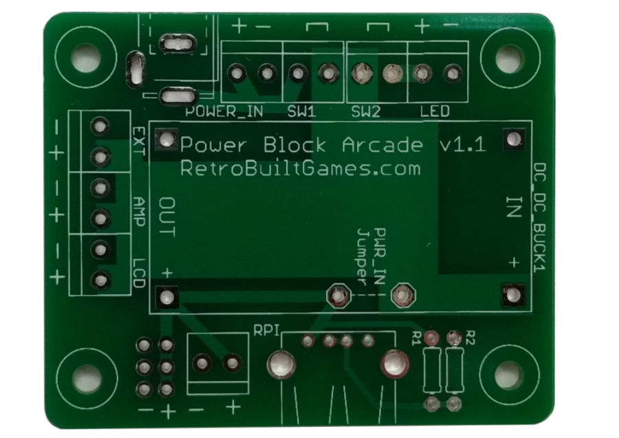
Remember: A switch (or jumper connection) is needed for "SW1" and "SW2". Power is not distributed from the "POWER_IN" without these connections.
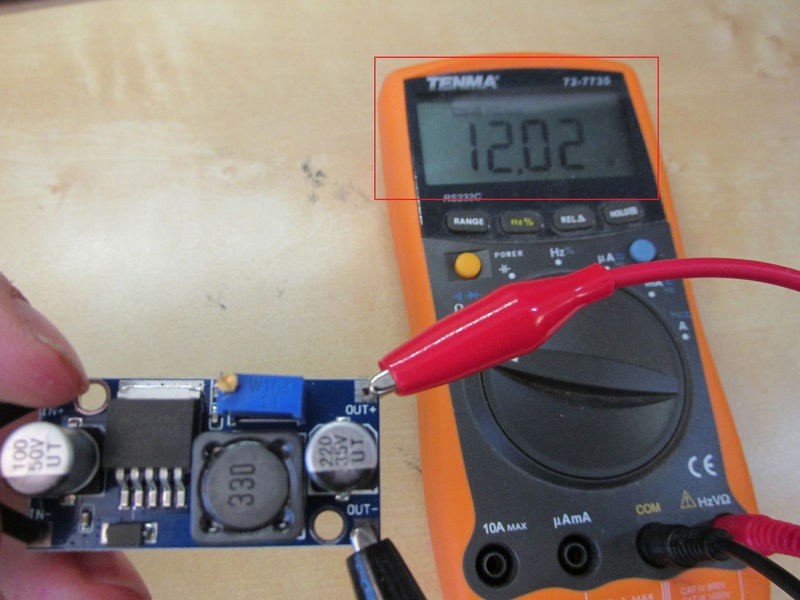
2) Adjust Voltage Regulator & Testing
The power block arcade gives you the option to build your arcade with either 5V power or something else (say 12V). If you choose something other than 5V, say 12V, and are using a Raspberry Pi in the arcade: You MUST use a voltage regulator to drop the voltage down to 5V before connecting to the RPi. See this for details.
Not using the buck/step-down/ voltage regular? Skip tp step 2.
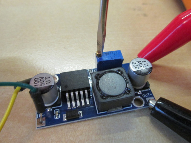
The majority of the cabinet electronics are powered off 12V, some require 5V. A DC-DC step down converter is for said electronics that require 5V input. The step down converter must be adjusted (turn the potentiometer knob) until ~5.15V is on the output. By default (i.e. out of the box) it's almost a straight pass through (with 12V input). USE A VOLTMETER when calibrating the output while turning the pot knob. If you skip this step and send 12V to your Raspberry Pi or JAMMA PCB you will regret it so much.

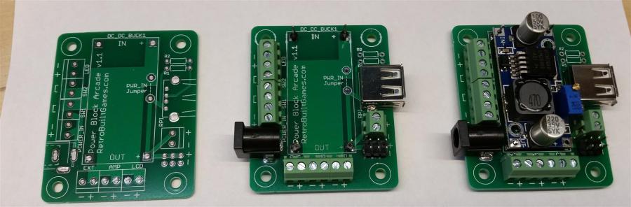
3) How to Assemble
Soldering the screw terminals are optional. Full assembly looks like the following:
That blue PCB (step down converter) is only for 12V arcade setups.
4.1) How to Wire: 5V, no stepdown converter
If you are using a 5V power supply, then the power block only serves one role: to distribute power. It does not regulate (or step down) the voltage. Since we are not using a voltage regulator, you need to jumper (solder a wire) to the "PWR_IN" connections.
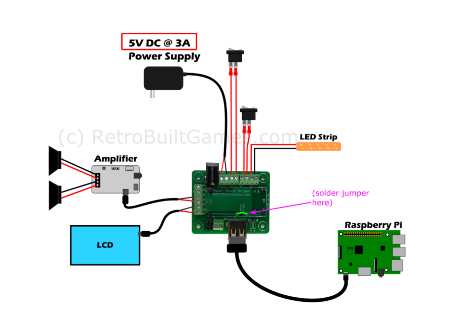 5V setup: be sure to connect jumper in-place of step-down converter.
Screw terminals are optional (you can buy the bare PCB and save few $). Wiring is the same without the screw terminals. In this scenario you are soldering directly to the PCB.
 5V setup: Same as previous, but on a bare PCB. Headers are optional.
4.2) How to Wire: 12V, use stepdown converter.
As shown in step 2, a wiring diagram with a voltage regulator (buck step-down converter) is wired in. Make sure the voltage converter is set to ~5V before powering on with a Raspberry Pi connected.
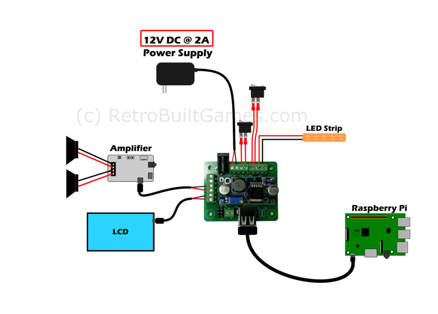 12V input with a step-down converter for 5V
5) What's R1 and R2 for?
The resistors R1 and R2 are a result of feature creep and are not required for an arcade build. However, if you are like me and find yourself with many devices (Cell phone, PS4 controller) that need 5V charging ports but with only a few high current chargers, the Power Block Arcade PCB can help. The Power Block Arcade PCB can be configured for "fast charge" or high current USB charging by adding some resistors. These resistors will create a voltage divider at the D+ and D- USB terminals. Some devices look for certain voltages on the data lines to know if the charging circuit can pull high current from USB. These resistors make the difference why regular USB ports charge slow versus yellow-colored USB ports or USB cell phone chargers.
I've only tested this voltage divider on the devices I have. The rest is unverified information from the internet- proceed with caution.
| Charge device | D+ | D- | Notes |
| iPhone | 2.0 | 2.0 | untested |
| iPad | 2.0 | 2.7 | untested |
| 2400mA | 2.7 | 2.7 | untested and risky for this module |
| Samsung phones/ PS4 controller | 1.2 |
1.2 |
tested! and working fine |
| unknown | D- shorted | D+ shorted | untested |
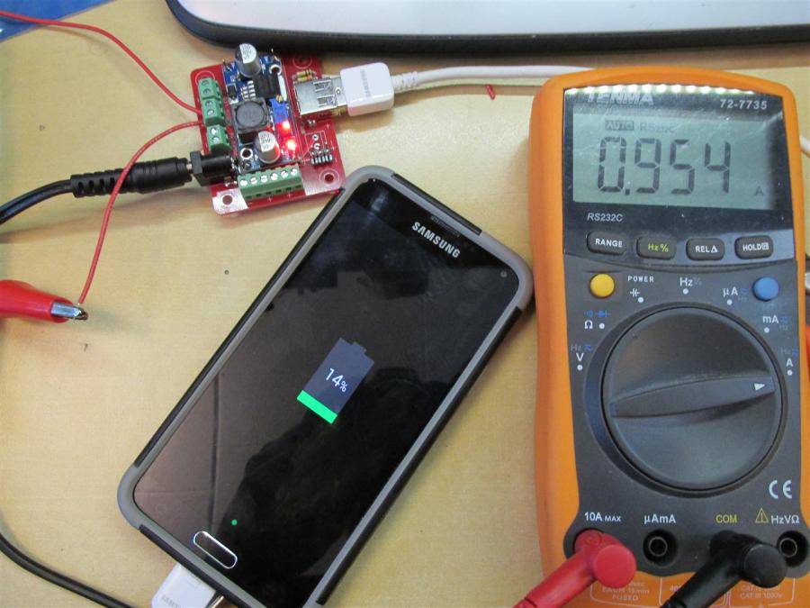 High current charging possible thanks to voltage divider on D+/D-. Older revision shown, this feature is present in current version.
Don't need a fast charge on D- and D+? You could also sub a resistor and an LED (for R1 and R2) if you like seeing an LED when power is present on the PCB. NEAT!
6) PCB layers and Extra Resources.
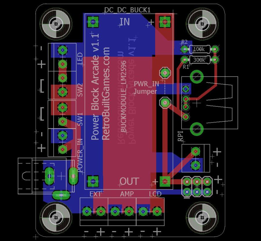
Version 1.1 has two switch terminations to control main power and backlight power.
Red shows where +V is distributed. Blue is Ground.
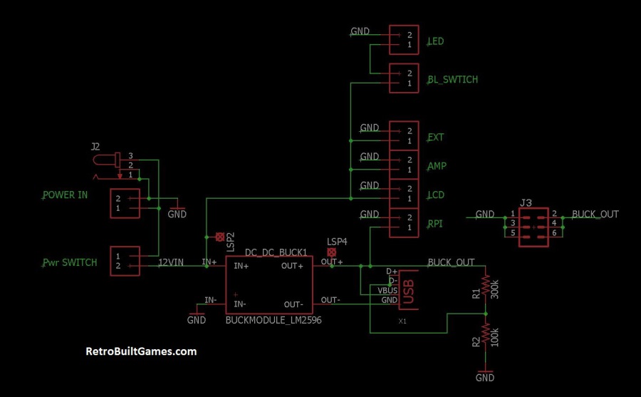 Ah I just noticed that typo on the BL Switch. BL= Back light for the arcade marquee.
© 2013-2023 Ryan Bates and © 2013-2023 Retro Built Games, LLC. All photos, designs, documents, and graphics (C) Ryan Bates. All Rights Reserved.
This site is best viewed on a desktop PC. Raspberry Pi is a trademark of the Raspberry Pi Foundation. ARDUINO® and other Arduino brands and logos published in the website are Trademarks of Arduino AG.